(or how I learned to stop worrying and love ambiguity)
This post covers the issues surrounding CAD collaboration and past approaches to resolving it. It then concludes with a concept of how decentralised digital model development could be undertaken in a manner that reflects the ambiguous environment in which collaborative design is experienced.
The Problem of Digital Model Orientated Collaboration
Modelling an architectural design in CAD almost never occurs in an isolated environment. Typically work is undertaken with at least one other person simultaneously in order to meet development deadlines. Unfortunately issues arise when participants wish to simultaneously change the same design element, or a set of design changes inadvertently effect another aspect of the digital model.
Recently I was asked to comment on a debate that was raging in the Vectorworks forums related to its minimal set of collaboration functionality. Whilst the forum thread initially begun as a feature request it soon evolved into rather heated debate over how collaboration functionality in CAD should function (if at all). Central to this online debate was the role internal offices processes and politics held in the success of a collaborative digital model. Whilst this is typically the most visible factor we must also keep in mind the mere introduction of digital models has significantly altered our collaboration psyche.
Representational Shift
Before CAD collaborative design development had minimal effect at the drawing level because it was understood that each sheet was an isolated representation of the proposed design. Irregularities on different sheets were accepted as a byproduct of the chronological drawing process or later amended with supplementary information. In a digital world we are unwilling to accept this representational ambiguity for two reasons: either the integrity of the digital model is so important to design documentation that it cannot be ignored, or psychologically the consumers of the data expect digital models to be consistent because 'the computer is never wrong'. Whichever expectation holds true it illustrates a subtle representational shift from drawings as a means to an end, through to the digital model as a means and end unto itself.
Perception of Precision
Conventional architectural representation is of limited precision due to the inaccuracies of the tools available and the small scale applied to most drawings to fit their chosen media, for example a sheet of A2 paper. In contrast the digital model has no defined scale and a high degree of fidelity because of a computers ability to manage large quantities of data quickly and accurately. This computing capacity raises the perception that a digital model is very precise when in fact it often has the same tolerances as a conventional drawing. As a consequence when inconsistencies are identified within a digital model they are viewed as failures of the process rather than as natural artifacts of the dynamic and inherently imprecise activity that is architectural collaboration.
Due to these representational and perceptional changes there is an increasing emphasis within the Architecture, Engineering and Construction (AEC) industry to consider the digital model as the outcome of the design process in place of a conventional set of production drawings. This shift in desired outcome has heightened the challenge when it comes to enabling multiple parties to efficiently manipulate the same digital model.Prior Teamwork Solutions
Various methodologies have been applied to the problem of enabling teamwork within a single digital model. A summary of these high-level approaches are: linked independent files, external document management, an intelligent master with satellites and an always connected, centralised digital model. Most CAD packages take advantage of one or more of these methods to enable their users to work within a team.
Linked Independent Files
Pros: Simple, supported within a wide variety of software, low barriers to entry
Cons: High management load, no warning of external changes, external data cannot be manipulated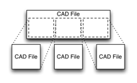 This is the oldest and simplest method of collaborative digital model building. Within CAD circles the process of linking is often called referencing or XREF'ing depending on the software vendor. A linked-file collaborative approach enables two or more people to work independently on different files whilst still having a reasonable idea of how the entire digital model is evolving. Due to its simplicity and relative maturity as a concept most CAD applications support some form of file linking, in some cases even across different file formats (e.g. dwg to dgn linking).
External Document Management
Pros: Applied on top of existing CAD platforms, often deeply integrated, provides a range of extra services
Cons: Requires purchase/maintenance of separate software, issues with lock-in and upgrade cycles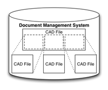 The primary advantage of using an external document management system in concert with CAD software is that it allows team members to overcome many of the shortcomings of the linked file approach without changing the CAD software users have experience with. Unlike conventional documents a digital model often spans multiple files which raises problems around data consistency and interpretation. AEC-specific document management tools have evolved to meet these issues and handle change management, clarification of naming standards and communicate digital model meta-data such as unresolved design issues. Increasingly these systems are also implementing automatic file conversion functionality (i.e. digital model to PDF or DWF) in order to increase accessibility of design information to all members of a design team.
An Intelligent Master with Satellites
Pros: Self contained collaboration, intelligent semantic-based permissionsCons: Requires complex synchronisation process, steeper learning curve for new users
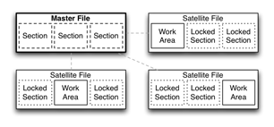 The evolution of Building Information Model (BIM) concepts within software such as Revit and Archicad has led to development of highly structured models capable of being edited simultaneously by multiple parties. This capability stems from the models ability to internally divide itself into a number of discrete areas which can be assigned user-specific editing permissions. In theory each user could then access and modify the same file but in practice network and disk I/O problems have limited availability and reliability. To overcome these hurdles copies (satellites) of the digital model are distributed to each user for editing on their local computer. Once the changes are complete a synchronisation process replicates the working model's changes back into the master model and updates the satellite file with other updates that have occurred within the master.
The benefit of such an approach is that all design and collaboration information is contained within the same digital file rather than being distributed amongst multiple resources on the network. Management overhead is minimised as the CAD platforms which employ such an approach understand rich architectural semantics allowing their collaborative capabilities to be relatively intelligent. From the end-user's perspective their experience is also improved as they are not dependent on network or shared resource availability and performance to undertake work.
A limitation of this and the linked file approach to collaboration is that users cannot make or propose changes to design elements beyond their set of allotted permissions. Consequently careful planning must be put into the assignment of model access rights to ensure that the team's working efficiency is not impeded. In rigid teams where responsibilities are clearly understood such a task may not be difficult, but in fluid teams this can be a significant challenge and an impediment to productivity.
An Always Connected, Centralised Digital Model
Pros: Everyone is always working on the same model, real-time collaboration, fewer management issuesCons: Requires a constant network connection, no production systems yet exist(?)
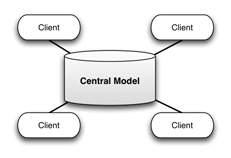 In a completely centralised digital model all information is stored at a single location such as an internally operated server or within a cluster on Internet. CAD users interface with the model via network connected devices and a piece of client side software that displays the data in a meaningful way (think Google Earth). As all write operations are performed at a single location these design changes can be viewed in real-time by team members connected to the system.
Management decisions still need to be made over who has the permission to change what and when, but in an always connected environment it is usually assumed model locking will occur at finer level than that employed within a satellite approach. This is generally because a satellite approach encourages the reservation of editing rights on a larger area than actually required. This is because unforeseen changes may need to be made and the risk exists that another party will modify a dependency such as a wall or other relevant design element. In contrast within an always connected, centralised model editing locks can be localised around specific areas because users have a real-time understanding the digital model and the context in which they are making their design decisions.
In practice a centralised model is similar to a satellite approach without the complicated synchronisation process. Unfortunately even in a world where the Internet has become ubiquitous, maintaining a network connection is still the greatest barrier to employing such an approach. As a result there are very few, if any, production-quality CAD tools that are based solely on this architecture. The most notable examples that come to mind are the IFC Server Project and Divercity research projects, both of which never left their testing environments. Given the increasing proliferation of the Internet throughout the developed world it seems inevitable that a CAD product based on such a collaboration architecture will reach the mainstream in the not too distant future.
Hybrid Approaches
CAD applications can mix and match these various collaboration architectures to reach a balance that suits their user's requirements and environment. MicroStation for example can make use of linked-file and central database collaboration architectures. Whilst most CAD applications store the digital model in memory and then save the changes to disk periodically MicroStation places its digital models within a relatively simple and open, file-based database system. Changes are recorded directly to disk and being a database multiple parties to read and write to the same resource (similar to Microsoft Access's JET back-end). Consequently MicroStation can employ a central database approach to collaborating or link independent file resources together in a more traditional manner. It must be noted that the central database collaboration functionality available within MicroStation is relatively limited compared to systems developed purely around such an approach but the fact it can operate in such a configuration makes it a very versatile collaboration platform.
Accepting ambiguity when the 'computer is always right'
Attaining an absolute answer from a process that is in flux until the paint literally dries is a difficult proposition. In the teamwork architectures described this need is met by having one 'correct' digital model around which we go to great lengths to preserve. Central to this mindset is that a digital model should be 'more correct' than a traditional drawing. Unfortunately at the end of the day the models we develop are just best guesses based on the information we had on hand at the time of authoring. If for some reason the context behind those guesses change, for example a wall is repositioned, it is the process by which we can adapt our design intentions to meet these changes that should be more important rather the processes followed to maintain a 'correct' digital model.
An alternative approach – snapshots and deltas
Assuming for a moment that the computer is not always correct how do we work collaboratively on a digital model in a manner that embraces this ambiguity yet still allows us to be productive? I don't have a definitive answer but what follows is my idea on how this could work based on an architecture that is distributed rather than relying on a single, all powerful point of reference.
Before explaining my alternative approach two I.T. concepts must be introduced: snapshots and delta encoding. A snapshot is a captured moment in time during the life of a piece of data. It is commonly used to enable the backup of data that is undergoing constant change such as databases. Delta encoding is the process of recording only the changes that have occurred to a piece of data over a period of time. It is more efficient than storing two different copies because generally data manipulation is a subtle affair (we add a door or move a wall) rather than an event which is completely destructive (the entire model gets deleted).
With these two concepts in mind my intention is to now describe a methodology for digital model collaboration that attempts to satisfy the seven Project Information Cloud principles of:
- Simplicity
- Modularity
- Decentralised
- Ubiquitous
- Situational Awareness
- Context Sensitive
- Evolutionary Semantics
The aim of the approach outlined in Figure 1 is to provide an intelligent way of understanding, comparing and merging distributed changes to the digital model. A secondary objective is to allow the participants to operate independently without tight managerial control which can be a major hindrance to productivity and creativity.
Within this architecture a snapshot can be simply a conventional CAD file but in order to satisfy the requirements of the architecture it requires a versioning index to be maintained which describes the history (authors and dates) of the digital model's snapshots. The recorded delta changes would describe in CAD terminology how the digital model has been manipulated, for example 'wall A was changed to a length of 10m'. Both the versioning index and delta changes could be maintained within the CAD file itself or stored externally as separate files or a series of database entries. For the purposes of this example it is assumed the versioning history is maintained within the snapshot whilst the delta changes are stored as separate individual files.
In the following example there are three design team members who work on the digital model at different times during the project's history.

Figure 1: An outline of the distributed CAD collaboration architecture based on snapshot and delta change concepts (click to enlarge)
A Fictional Description of Events
Andrew the architect creates a new digital model and sets to work describing the building in CAD (1). Once he has determined the basic design he meets with Carol the consultant who is charged with developing the interior fit-out of the building. It is at this point Andrew creates a snapshot of the digital model to provide Carol with a copy to work on (2). Once Carol understands what Andrew has been up to she begins adding new design elements to meet the specialised working needs of the client (3).
With her part of the design complete Carol meets with Bob the builder who has offered to help out on some construction detailing she did not know how to solve. Carol creates another snapshot of the project file and emails it to Bob (4). Bob quickly completes the detailing and resolves an issue with the placement of one of Carol's dividing walls near a structural element. Bob then arranges to meet with Andrew the architect after the weekend and go over the things he and Carol have worked on.
On the night before their meeting Bob emails Andrew a snapshot of the digital model (5). On opening the model Andrew is notified by his CAD software that the model has been modified several times by Carol and Bob for different reasons. Unfortunately over the weekend Andrew has also been working on the model which leaves him confused about who has changed what exactly and why. Looking at the work log stored within the file he determines that Carol modified model before Bob (6). With this knowledge Andrew points his Internet browser to Carol's secure file storage and downloads the file containing all the relevant delta changes she made to the digital model he originally provided her (7). The CAD software then automatically regenerates Bob's delta changes through comparison of the snapshot available and Carol's delta changes (8).
With all the relevant delta changes at hand the CAD software displays a chronological overview of the digital model's evolution from the perspective of each participant's input (9). The software then determines a list of design issues through the analysis of delta changes made by each of the design participants. For the most part the individual changes to the digital model work well together but a couple of problems do arise around Bob's repositioning of the dividing wall and some of the changes Andrew has later made (10). Andrew generates a report which includes a breakdown of these issues alongside relevant plans and sections to discuss with Bob. While the report is printing he also calls Carol to see whether she has any preference on the final location of the dividing wall as she was the person to originally propose it. Fortunately for everyone involved Carol does not mind where the wall is placed leaving the decision in the hands of Andrew and Bob.
Whilst overly simplified the hypothetical example above does illustrate that a distributed approach based around snapshots and delta changes could be a worthwhile and flexible addition to an architects collaboration vocabulary.
Benefits of a Distributed Approach
A significant benefit of a distributed approach is that no external systems have to be maintained and participants are not reliant on network access to undertake work. Compared to the satellite model a distributed approach can work with unsophisticated data models plus there are no concerns around editing permissions as anyone who has a copy of the digital model is free to make changes.
Conventionally change conflict is viewed in a negative light which leads to restrictions being placed on the digital model at the expense of the creative process. In the approach just described anyone can potentially change anything within their copy of the digital model. Rather than focusing on restricting access to the model emphasis is placed on understanding of how these design conflicts arise, navigating a way through this potential minefield and finally reaching a consensus that it suitable to all parties.
Drawbacks Compared to Alternatives
Compared to centralised systems the actual process of communication is not handled internally within the model or through a defined external system. The architecture simply defines three components: snapshots, deltas and versioning logs, that need to be exchanged between parties alongside and complimentary to other design discussion. Rather than being the center of attention this approach is intended to work alongside existing communication systems such as email and document sharing services.
Such an architecture is not a worthwhile choice if the design team is avert to disagreement and uncertainty in the exact state of the digital model. Team members who operate at a managerial level would gain the lest value from such an approach because unlike centrally managed and monitored collaboration a distributed model does not have an easily accessible 'correct' answer. The process of understanding how the model is progressing would be assessed through communicating with those involved and accepting the fact the digital model is somewhat intangible and not as precise or reliable as initially perceived.
Conclusion
With the digital model becoming the focus and eventual outcome of design development collaboration within this medium is gaining increasing importance. Currently there are four different approaches to digital model collaboration that can be applied within software tools such as CAD. These varied approaches can also be applied simultaneously within software products to provide even more collaboration flexibility to design teams. Unfortunately the majority of these collaboration approaches lead to highly centralised processes that place an emphasis on consistency over flexibility. A decentralised approach using snapshot and delta change concepts would facilitate a more efficient and fluid design collaboration environment which encourages discussion and compromise in place of conformity and hierarchy.