All architecture requires some form of structure in order to stand up. The size and layout of the structure can be instrumental in the success or failure of a building.
Revit provides several structural objects intended to aid defining and sizing the elements of structure within the building model. In this section we will use some of these tools to establish the structural grid used by Le Corbusier in composing the Villa Savoye.
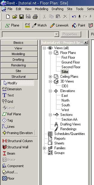
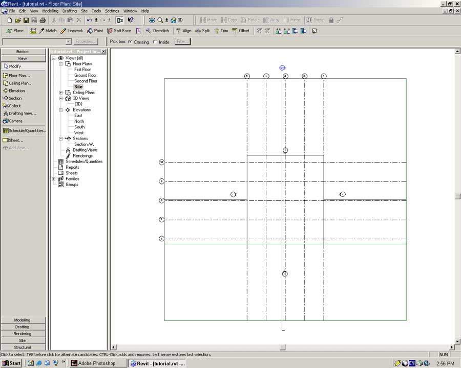
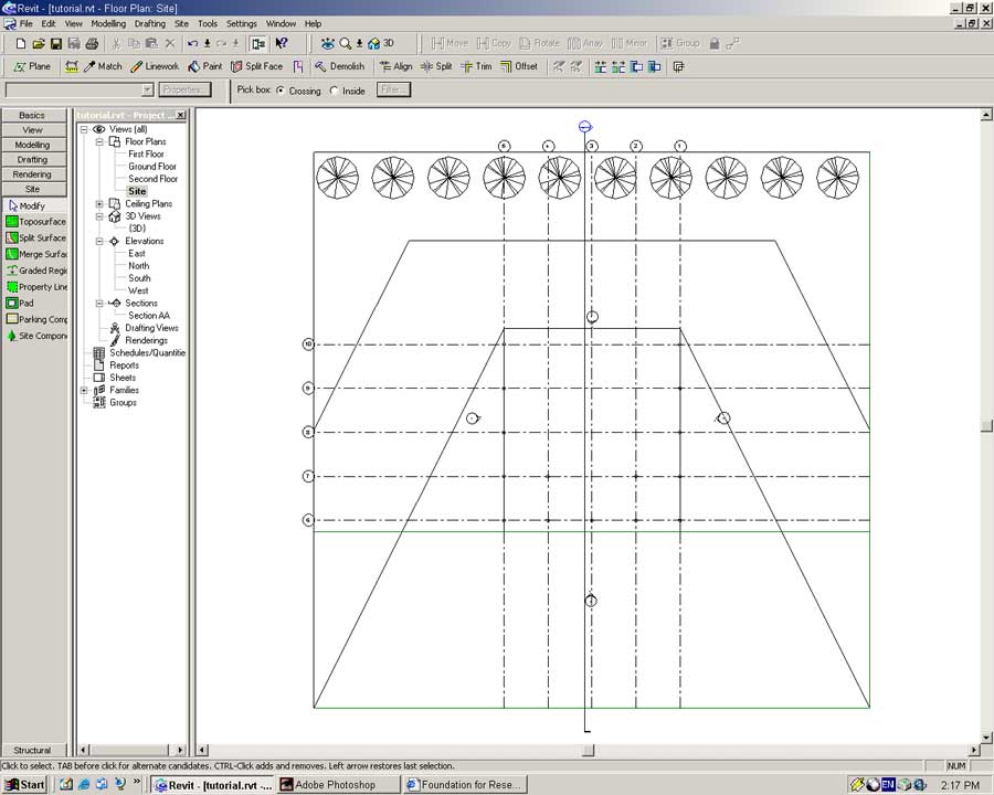
Open the Site plan.
If you have not already noticed opening the other views will not show the site. This is on purpose and is set in the View Range section of the View Properties dialog. This feature is enabled so that the view does not become cluttered with information.
Select the Reference Plane tool from the Basics Sidebar. Construct two reference planes along the southern and eastern perimeters of the site. These will act as guides for placement of the structural grid.
Rather than randomly placing structural elements we will build a structural grid to act as a guide for us. By default the structural tools are not shown in the Sidebar. Right click on the Sidebar, from the pop-up menu select Structural.
From the Basics Sidebar select the Grid tool.
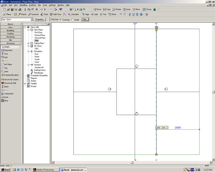
Move the pointer over the southern perimeter. A distance scale will appear. Move the pointer until the distance reads 21000 and click once to begin placing the grid.
Move the pointer vertically up to the northern perimeter and click again.
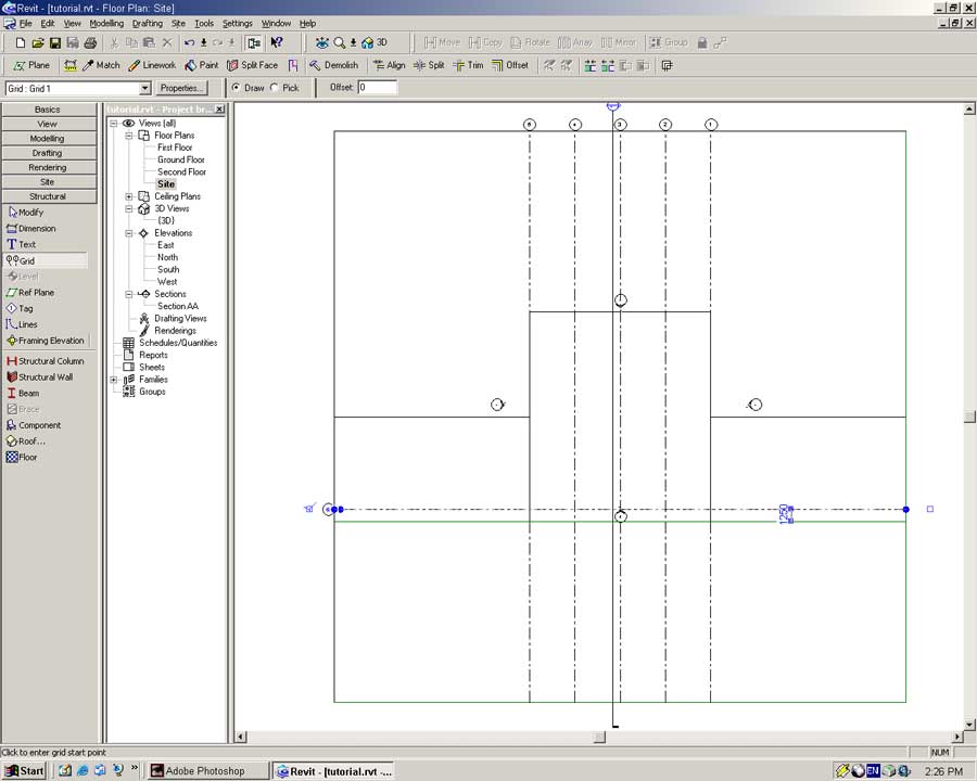
The first line in your structural grid should be established.
Select the gridline and modify its distance to the reference plane to be 20500.
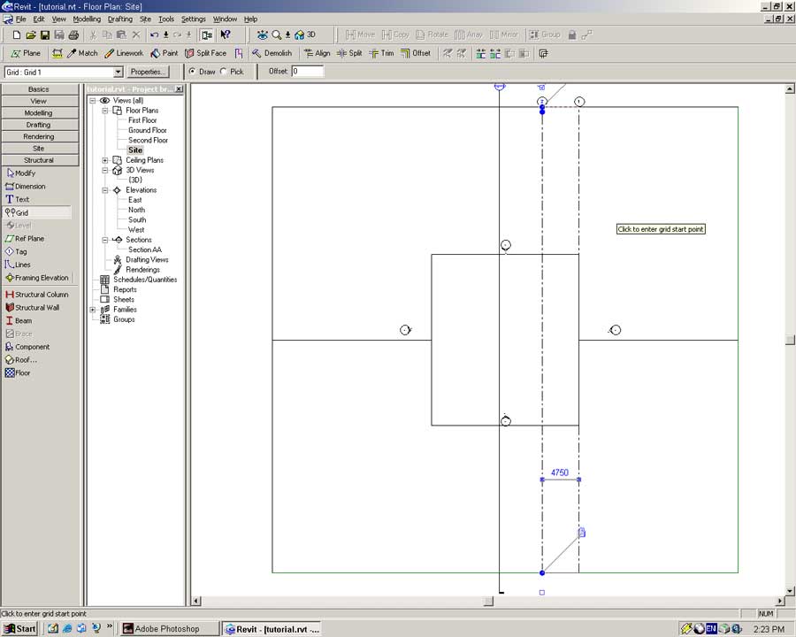
Using the Grid tool again place another vertical gridline 4000mm to the left of the first.
We actually want the gridline 4750mm from the first. Using the Modify tool move the new gridline to be 4750mm from the first. To do so click on the distance dimension between the two lines and type 4750 (Enter).
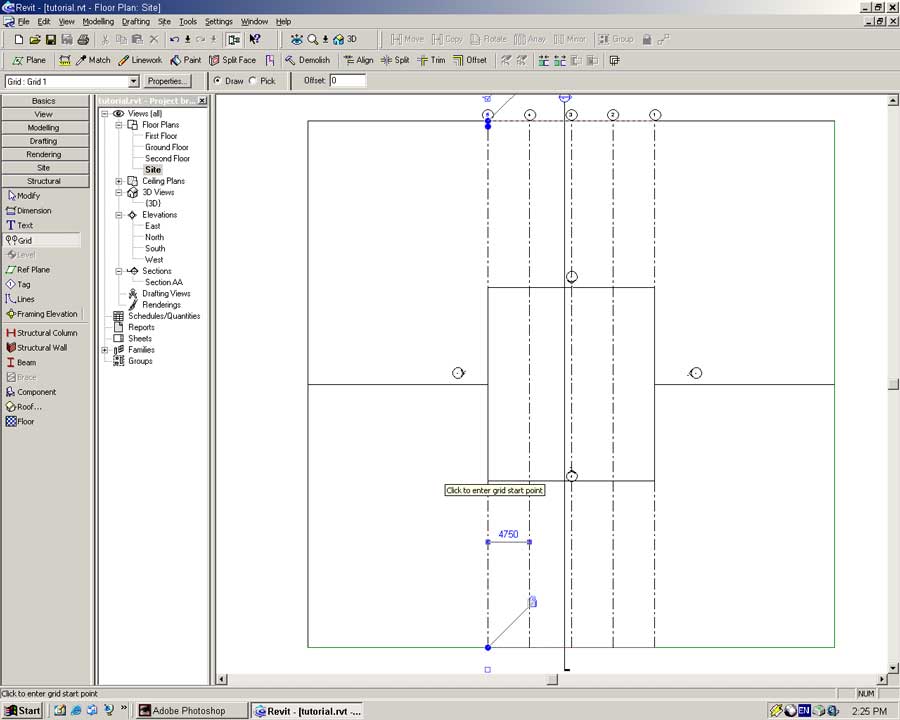
Repeat the process three more times to get the following vertical gridlines.
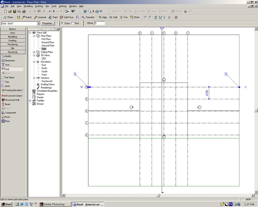
Place a horizontal reference plane 19000mm up from the southern perimeter.
Using the Grid tool place a structural gridline 1000mm up from this new reference plane. Once placed modify the distance of the gridline to be 1250mm from the reference plane as shown below.
Place four more horizontal gridlines spaced 4750mm apart as shown by the following.
With the structural grid created we will take a quick look at the Elevation tool.
Zoom in on the Southern Elevation object (a circle with a triangle pointing up). As it is now the South Elevation view will be within the space of our building. What we will do is move it down out of harm's way.
Using the Modify tool select the Elevation object.
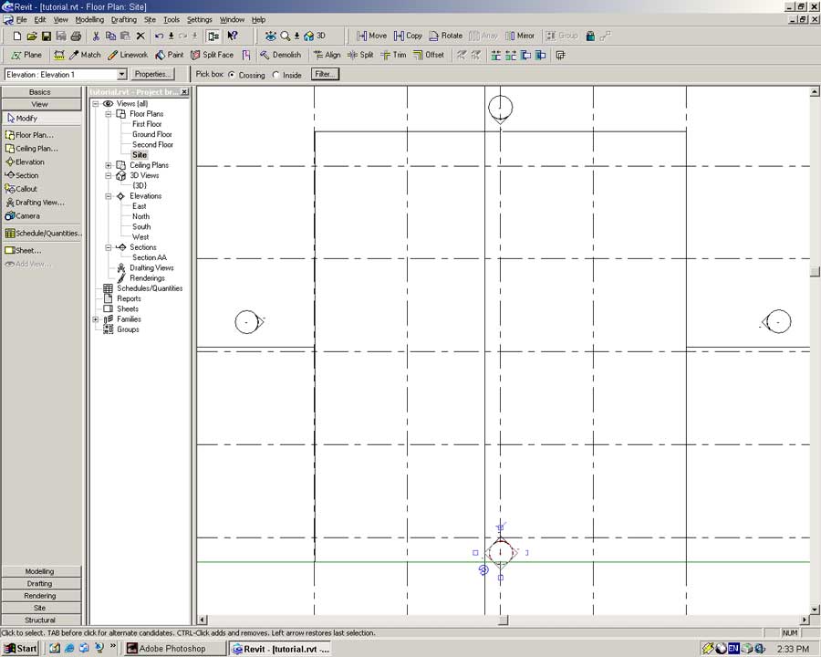
The object will change to have four triangles around the circle, complete with checkboxes and a rotation symbol.
By enabling (or disabling) a checkbox a new view is created (or deleted). The new view is built from the position and direction of the Elevation object at the time of creation.
A single elevation object may have four views associated with it.
The rotation icon allows freehand rotation of the Elevation object by clicking, holding and moving the pointer up or down.
Another more accurate method of performing a rotation is to use the Rotate tool.
![]()
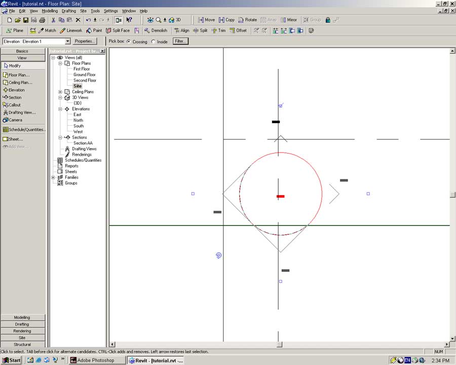
With the object selected invoke the Rotate tool by clicking on it once.
The toolbar below the Angle tool will change to reflect the options available within the Angle tool. In the angle textbox type a value (45) and press (Enter).
The object will be rotated in a clockwise direction about its centre point.
To undo this rotation (or any previous command) press CTRL and Z and the same time, or from the menu select -> Edit -> Undo.
The easiest way to move an object is to click and hold on the object and drag it around the screen.
To illustrate a more accurate method we will use the Move tool.
With the South Elevation object selected click on the move tool. The pointer will change to the Move icon.
Click once anywhere on the screen to define a point from where the move distance and direction will be taken.
Move the pointer vertically down the screen. Type: 8000 (Enter)
The Elevation object will move south 8000mm as shown below.
Uncheck the ticked checkbox on the South Elevation object to delete the old South view.
A dialog box will appear asking if you wish to delete the associated views. Say yes to this question and the old South Elevation will be deleted.
Once this is done recheck the same box to create an Elevation at the new location.
In the Project Browser right-click on the new view and select Rename. Name the new elevation 'South' to avoid confusion.
With that bit of housework complete we will make some structure!
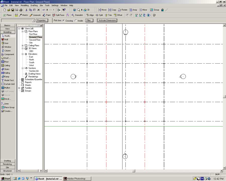
Open the Ground Floor view. Notice the site is not visible in this view but the structural grid is.
In the Modelling Sidebar select the Column tool.
By default Revit only loads one type of rectangular column at startup.
But the columns in the Villa Savoye are circular, what do we do?
Fortunately Revit provides a library of components and within this library is a circular column. (Phew)
Press the Properties button to bring up the Column object's properties.
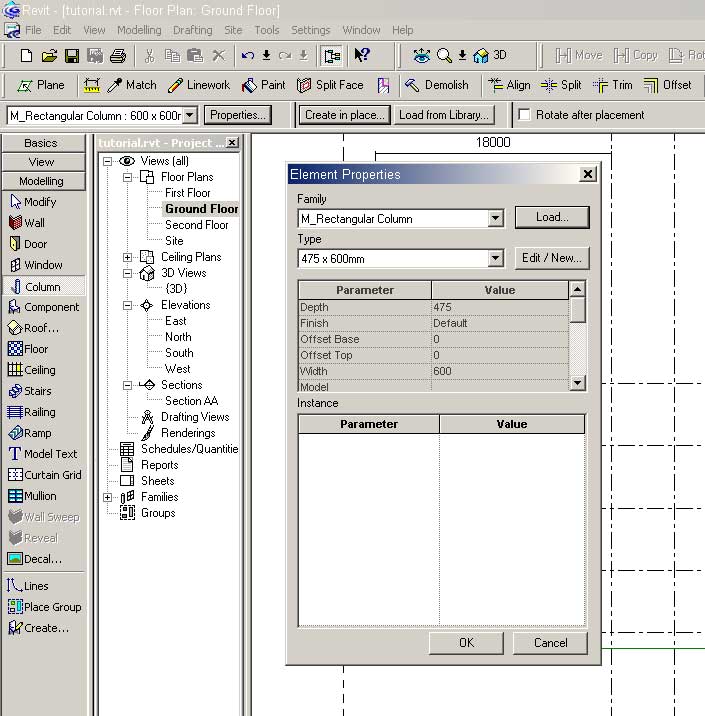
In the Family section at the top of the dialog press the Load button.
This enables us to load new components into Revit to use in our model.
The Load Family dialog will appear.
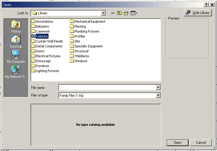
A file browsing window will open. Revit has many libraries broken into Metric and Imperial dimensions.
The Revit objects in this tutorial can be found in Revit's Metric Library folder.
In Revit's the Metric library browse to: Components -> 31 concrete -> concrete structure -> columns -> Concrete_round_M.rfa.
Select the file and press Open to load the family into the Revit project.
Back in the Family Dialog the 'Concrete_round_M' should be selected.
In the Type box select '300mm Diameter' and press OK.
Move the mouse over the intersection of the bottom left structural grid lines and click the mouse button to place a column.
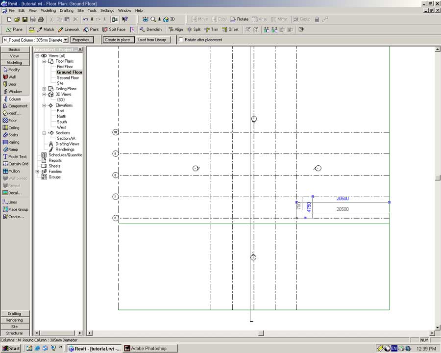
Place columns along the bottom, left and right perimeters and two columns in the positions shown below.
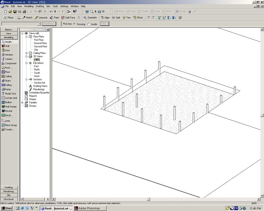
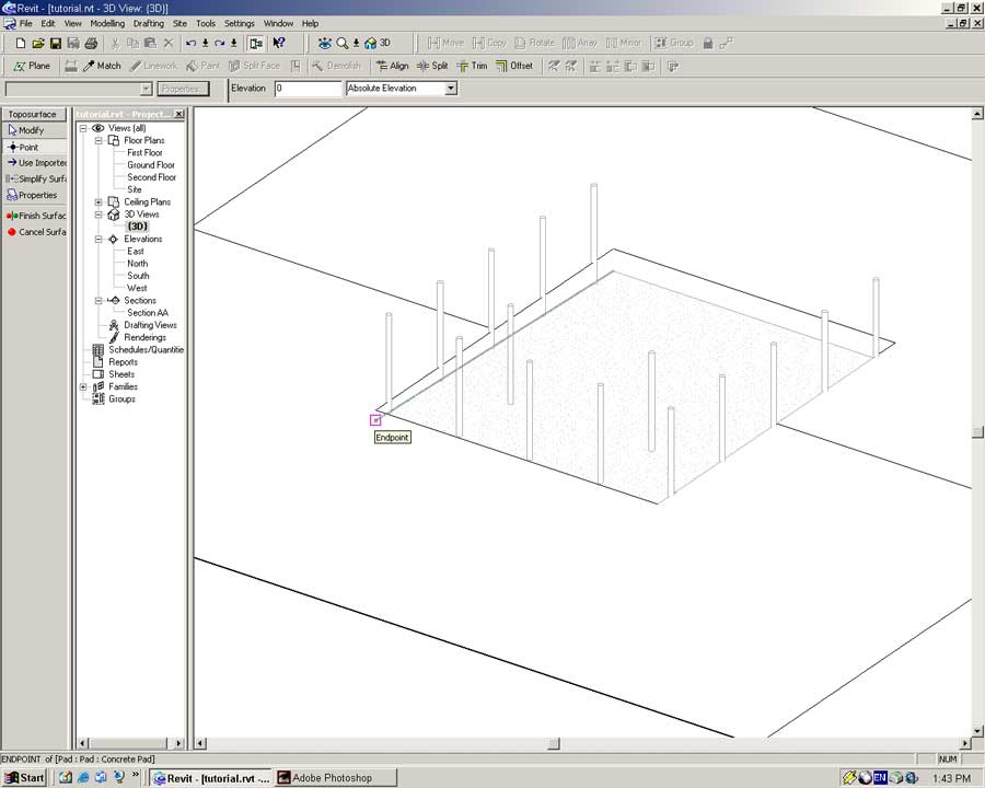
Switch to 3D View. You should see something similar to the following.
With the Modify tool enabled select a column and bring up its properties. Either:
- From the menubar select -> Edit -> Properties
- OR Press the Properties button on the toolbar
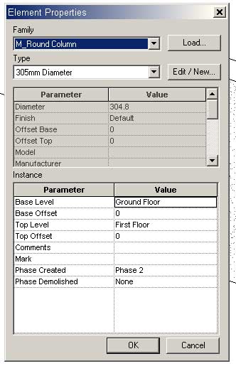
The bottom section of the dialog is devoted to unique parameters pertaining to this particular instance of the column object.
Base Level: Sets the vertical beginning of the object.
Base Offset: A distance above or below the Base Level to begin the object.
Top Level: Sets the vertical end of the object.
Top Offset: A distance above or below the Top Level to end the object.
Set the Top Level dropdown to Second Level and press OK.
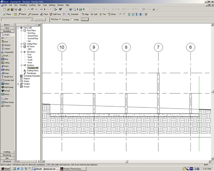
The selected column will change height. Open Section AA to see that the column now extends to the base of the Second Floor level.
Go back to the 3D View. With the Modify tool drag a box around all the columns.
This will select a lot of objects we do not want (such as the site and concrete pad).
In the toolbar press the Filter.. button.
A dialog will appear on screen. Uncheck the Site (Pads) and Topography boxes and press OK.
With a group of objects of the same type selected it is possible to universally apply settings.
To do so bring up the column properties, (press the Properties button).
In the Top Level dropdown select Second Floor and press OK.
This will extend the columns from the ground to the top of the building.
Bringing in the Bulldozers
From the 3D View you may have noticed the ground level is above our concrete slab.
We will fix this by modifying the geometry of the site.
With the Modify tool select the Toposurface object.
Press the Edit Surface button to edit the points of the surface.
On the Sidebar select the Point tool.
Place a new point at the position shown below (the top corner of the concrete slab).
Repeat the process for the three other corners of the pad.
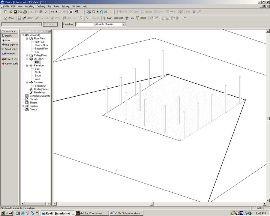
Click on the Finish Surface button.
With the site selected bring up its properties (Right-click -> Properties)
In the dialog set the Material parameter to: 'Site - Grass'
Press OK to close the dialog.
Just for fun we will add some trees to the northern perimeter of the site. Objects such as trees, people, doors and stairs can be very good indications of scale within two and three-dimensional models.
Open the Site Plan and zoom the view out so that the entire model is visible.
The quickest way to do this is by either:
- Right-clicking in the model window and in thr popup selecting -> Zoom to Fit
- OR from the menu select -> View -> Zoom -> Zoom to Fit
Before we can place any trees we will need to load the tree library into memory.
From the menu select -> File -> Load from Library -> Load Family...
In the open dialog browse to the 'Planting' directory and open any of the five planting options.
From the Site Sidebar select the Component tool.
![]()
Objects related to the site but not the building fall under this category. Any component related to the building will be created via the Component tool.
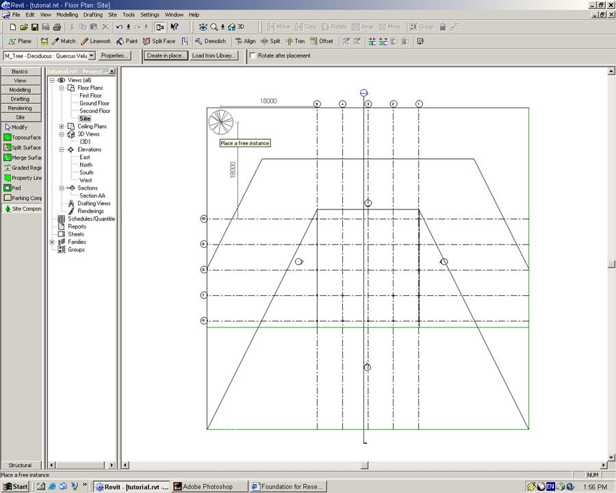
In the type dropdown select a type of tree you would like to place.
With the Site Component tool enabled move the pointer 18000 above and 18000 to the left of the structural grid, (in the top-left corner) and click once to place a tree.
Rather than placing a whole lot of trees manually we will multiply the single tree we have placed using the Array tool.
With the Modify tool select the tree object.
Activate the Array tool from the toolbar and click anywhere in the drawing window to begin creating an array.
By moving the pointer to the left or right a distance and angle will be displayed. This distance and angle defines the linear separation between individual elements of the array.
Move the pointer horizontally to the right so the distance indicator reads 6000mm.
Click the left mouse button once to define the separation between the elements.
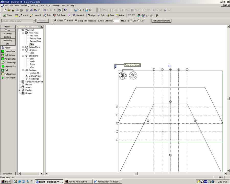
In the number field type: 10 (Enter)
An array of 10 trees will be created spaced 6000mm apart from each other.
With our landscaping complete we will now really get into building our villa. To start with we will define a flat white material and apply it to the columns.
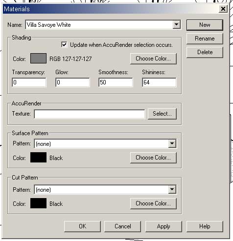
From the menu select -> Settings -> Materials
In the Materials dialog press the Duplicate button to create a new material based on the one currently selected.
In the name field type: Villa Savoye White (Enter)
In creating our material we will use the AccuRender Material library. AccuRender is a rendering programme built into Revit that will let us make quick but pretty renderings of our model. An extensive library of pre-defined materials ships with AccuRender.
To access the AccuRender material library press the Select button in the AccuRender field.
Click on the AR2_ACCUREND library.
In the long list of available materials select 'Stucco, white, textured' material. A preview of it will appear on the right.
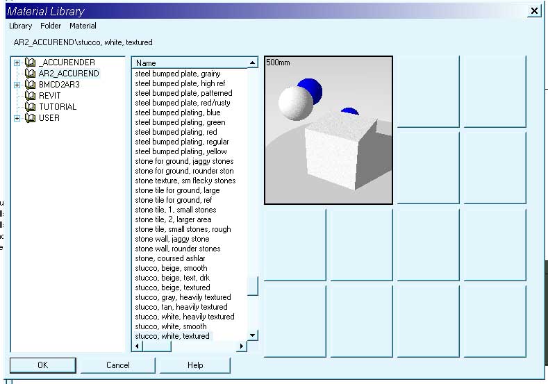
Press OK to select this material.
Notice the Smoothness and Shininess fields have changed because we have 'Update when AccuRender selection occurs' enabled.
Press the OK button to close the Materials dialog.
Open the {3D} view. Using the Modify and Filter.. tools select all the columns and bring up their Properties.
In the Type field press the Edit/New button.
In the Type Definition dialog press the Duplicate button to create a new object type based on the Round Column.
In the name field type: Villa Savoye Column (Enter)

Set the column diameter to 250mm and its Finish to Villa Savoye White.
Press OK in both dialogs to accept the changes made to your columns.