Laying out and printing your model is often the part left to the last minute and sometimes the most difficult to do. Fortunately print layouts in Revit are relatively straightforward and can be done at any stage of the modeling process.
Using the model of the Villa Savoye we will setup and layout and sheet for printing.
Revit comes with a set of default page layouts. They are heavily branded and overly complex for what we want to achieve today. To start with we will make a new title block Sheet.
From the menu select -> File -> New -> Title block...
In the dialog select the A3 metric.rft file and press OK.
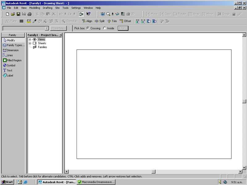
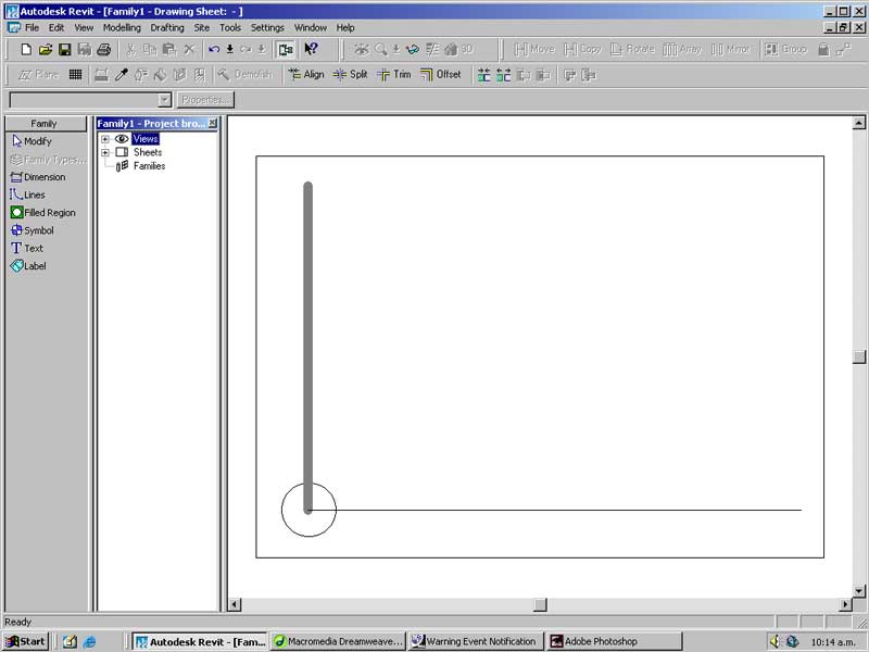
You should see something like the above.
The box represents an A3 page and the limited set of tools in the Sidebar are your drawing options. It is at this point where Revit acts very similar to any drawing programme you may have used in the past apart from the Label tool (which we will cover shortly).
With the Lines tool draw the following on the page using any dimensions you like.
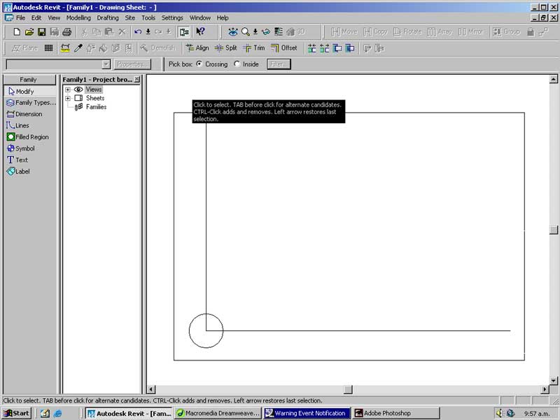
Select the bottom line. In the Type dropdown next to the Properties button select Wide Lines. The line will become thicker.
From the menu select -> Tools -> Object Styles
Unroll the Title Blocks section by pressing the plus symbol next to the text.
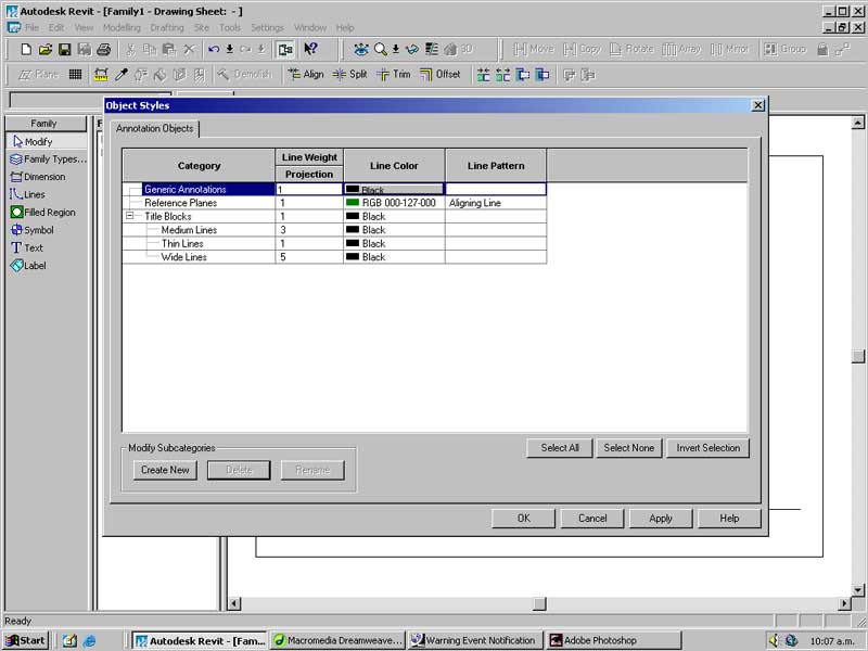
In the dialog box select the Title Blocks section and press Create New.
For the New Subcategory enter the following:
Name: Wider Line
Subcategory of: Title Blocks
For the Wider Line subcategory set the Line Weight Projection to 14 and Color to grey. You should have the following.
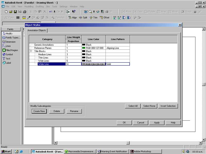
Press OK to close the dialog.
Select the left hand, vertical line and bring up its Type to Wider Line.
Select the Filled Region tool from the Sidebar.
Using the Lines -> Circles tool create a new circular region above the existing circle.
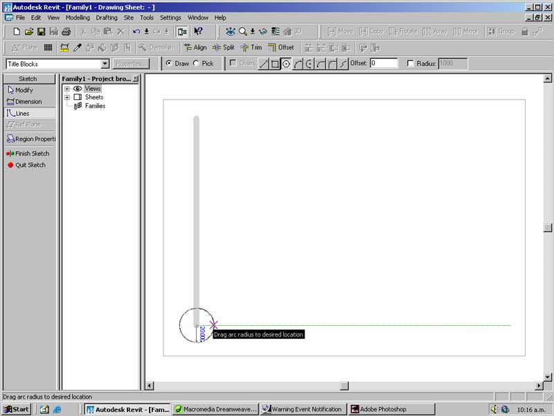
Press the Region Properties button in the Sidebar.
In the dialog select Edit/New...
We will just edit the existing Filled Region 1 properties. Set the following:
Cut fill pattern: Solid
Color: Red
Press OK twice to accept the properties and press Finish Sketch.

Using the Trim command trim the two Lines to the perimeter of the circle.
This is achieved by doing the following:
Press the Trim command.
Select the circle perimeter.
Click on the piece of the straight line you wish to keep.
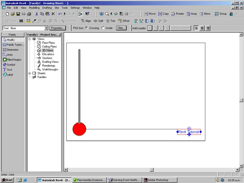
With the Text tool create a text box in the bottom right corner of the page below the horizontal line. Type: Revit Tutorial.
Labels are pieces of text that are defined in your Revit model rather than in the title block. A label is something that would change for each sheet (such as drawing number, date, project, ect.)
Select the Label tool from the Sidebar.
Click in the bottom-left corner below the horizontal line.
In the dialog in the Parameter list select: Drawn By
In the Value box enter: My name goes here
Press OK to place the label.
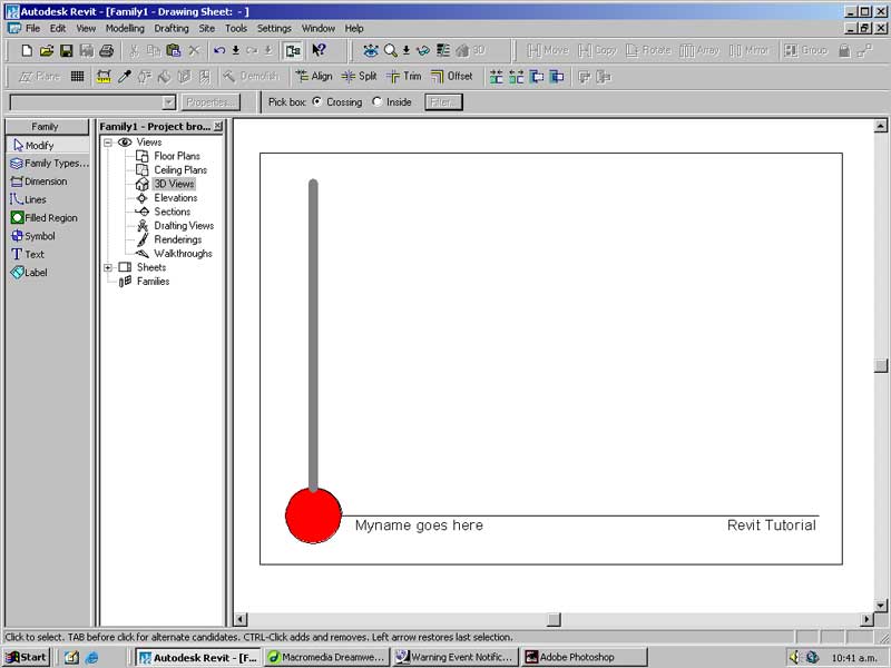
That is our basic title block complete. You could spend more time customising the text and layout of the graphics but for what we are doing this will be fine.
From the menu select -> File -> Save
In the dialog browse to your working directory and name the file something you will remember.
Once saved close the Title Block and go back to your model.
From the menu select -> File -> Load From Library -> Load Family...
Browse to the directory where you saved the Title Block and open it.
From the menu select -> View -> New -> Sheet
In the dialog select the name of your Title Block and press OK.
A new Sheet will be inserted into your model file using the template we just defined.
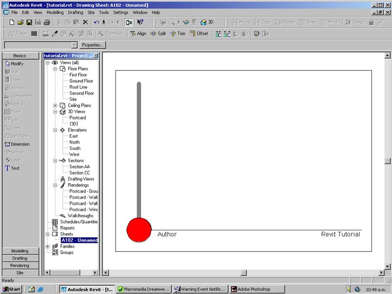
With the Modify tool select the new sheet.
Press the Properties button.
In the dialog under Drawn By type your name and press OK.
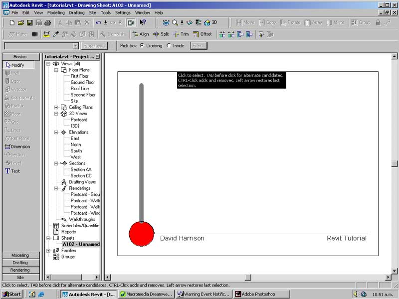
Your name will be entered into the Author section of the sheet.
This is really handy when you have lots of similar, but different information entered across a range of Sheets.
Now we will set up some views to place on this sheet.
It is possible to use the default views (eg. Site) on the sheet but we usually want to see more detailed modeling information onscreen than on our printed sheet.
As a compromise we will duplicate the Floor Plan: Site view and set it up ready for printing.
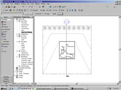
From the Project Browser right click on the Floor Plans: Site view and select Duplicate.
A new Floor Plan will be created named Copy of Site.
Right-click on this view and Rename it 'Site Plan' (so there is no confusion).
Double click on this view to ensure it is opened.
Right click in the modeling window and select View Properties. Enter the following:
View Scale: 1:500
Detail Level: Fine
In Visibility press the Edit button.
Turn off Annotation Categories: Grids, Elevations and Reference Planes.
Press OK to accept the new View Properties.
Open the Sheets -> (Sheet Name you just created)
From the Project Browser click and drag the view Floor Plans: Site Plan onto the sheet layout. A red box will appear delimiting the area the view will take up on your A3 sheet. Left-click once to place the view.
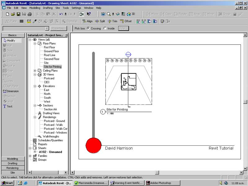
Select the newly created view. In the Type dropdown select Viewport: Section 3.
It is possible to create custom view tags for your sheets but this tutorial will not cover this.
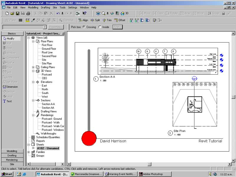
Using the same techniques as outlined above bring in some more views into the sheet.
Below I have duplicated Section AA, set its scale to 1:200 and hidden a few Annotations that were distracting.
Finally lets bring in a rendered image into this sheet.
Rendered images must be rendered to the correct size when performing a raytrace.
Open the Postcard view from the Project Browser.
Select the view and press the Size: Modify button on the toolbar.
In the dialog set Change to Scale (locked proportions) and set the Width of the image to 190mm.
Press OK to resize the Postcard view.
Select the Rendering sidebar and select Image Size...
In the dialog set the resolution to 150dpi if it is not already and press OK.
Select the Raytrace tool and press Restart in the toolbar.
Once complete make any adjustments to the brightness and contrast and then Capture the Image.
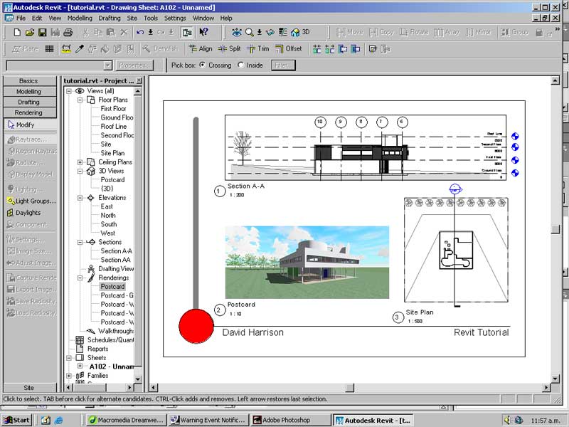
Open the Sheet layout and drag the captured image onto the sheet.
Below is my completed sheet for this exercise.
There is plenty more that can be done to this sheet.
The View Titles can be modified and the Title Block worked up to show more information. Information on how to do this can be found in the Revit online help.
Printing and Exporting
Printing and exporting a sheet is relatively easy in Revit.
From the File -> Export menu you can export an active sheet to an image file (tiff, jpeg, ect) for editing in Photoshop or to PDF for publishing on the web.
To print an active sheet select File -> Print
In the dialog select the printer you wish to print to.
Press the Setup button in the Settings section.
In order to get colour and bitmap prints ensure in the Appearance section number of colours is set to Printer Setting.
If not enabled you will probably just print out your line work.
Press OK and Save the printer settings.
Press OK to print the Sheet or Preview to see what it will look like on paper.
Conclusion
Hopefully by now you have a reasonable understanding of Revit and how it can help you develop and document your designs. This tutorial only scratches the surface of Revit's potential and is by no means a definitive guide.
For more information on using Revit refer to its online documentation or visit the Autodesk website and browse to the Revit section.