With the basic shell complete we will move on to constructing the elements on the rooftop. To do so we are actually going to draw over an original plan by Le Corbusier. This technique can be very handy for modeling buildings from existing plans when exact dimensions are unknown or unnecessary.
Before we begin download the following image onto a local folder.
In Internet Explorer Right-click on the link below. In the popup select Save Target As.
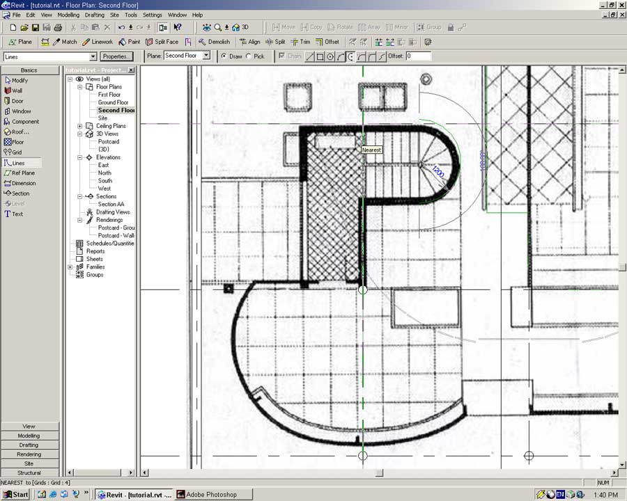
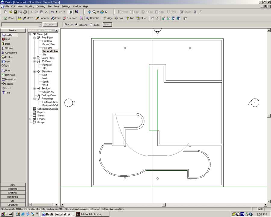
Open the Second Floor view.
From the menu select -> File -> Import -> Image
Browse to the location of the image on your local drive and press Open.
Place the image in the middle of your building by left-clicking.
The image will not be visible as it sits below the roof. To see the image we will hide the roof.
Open the View Properties for the Second Floor. Press Edit in the Visibility field.
Uncheck the Roof option in the dialog and press OK.
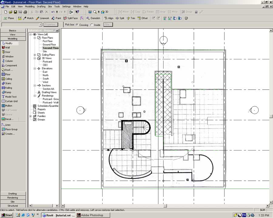
Position and scale the image by clicking and dragging on its corner points.
Ideally the image should match up with the external walls modeled previously.
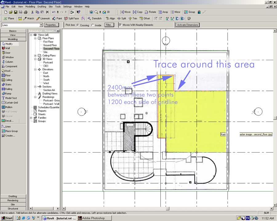
With the image aligned with the model we will firstly cut away part of the roof.
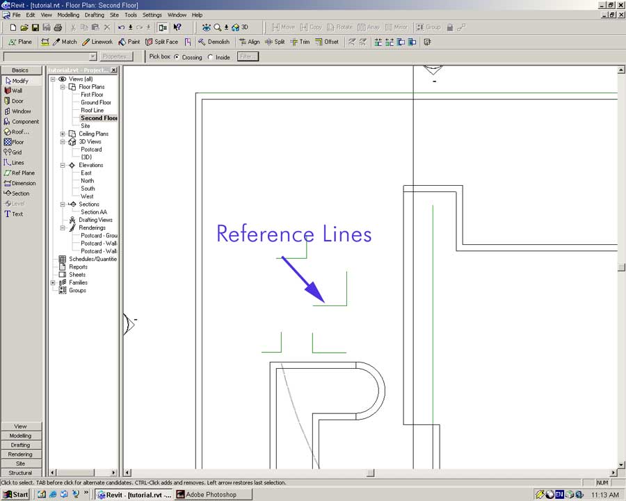
Use the Lines tool in the Basics Sidebar to trace around the lines indicated below.
In the View Properties go to the Annotation Categories tab and hide Raster Images.
Make the Roof visible again by using the same technique.
Open the {3D} view and using the Modify tool select the roof.
With the roof selected open the Second Floor view and press the Edit Sketch button on the toolbar.
The trace lines made previously will be visible in this view.
We will modify the footprint of the roof to take account of the opening.
Using the Modify tool select the right hand roof line and delete by pressing the DELETE key or from the menu select -> Edit -> Delete.
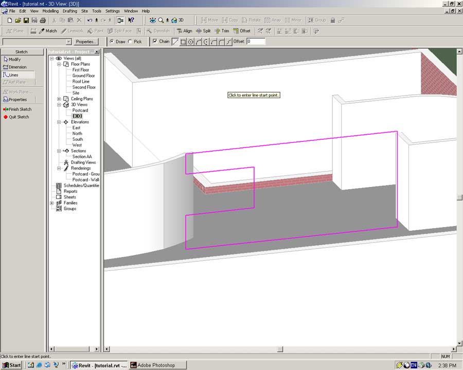
Select the Lines tool from the Sidebar and enable Chained lines from the toolbar.
Begin placing the new footprint line from the top-right corner of the roof to the location of the first trace line.
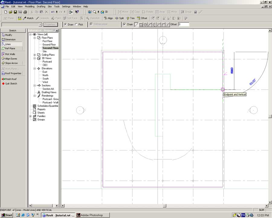
Continue tracing around the lines you created earlier (ensure Chain is enabled).
You will notice slope definitions are enabled on the new lines that you create.
After the new lines have been placed use the Modify tool to turn off any slope indicators.
Press Finish Roof from the Sidebar.
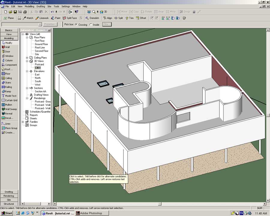
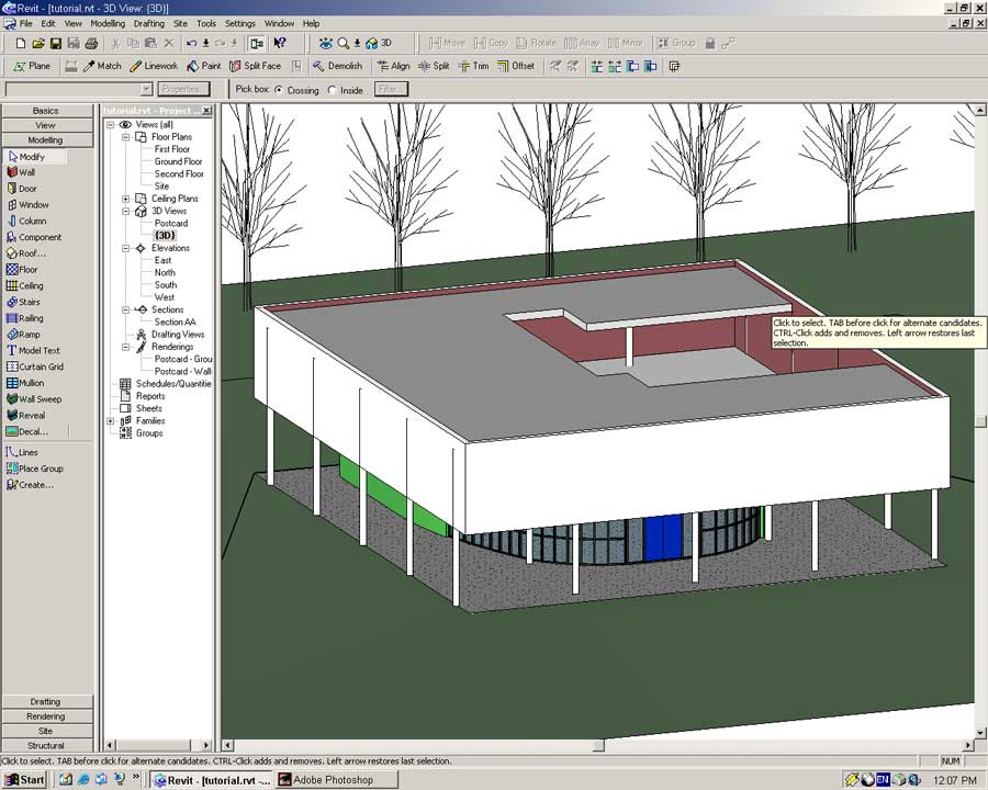
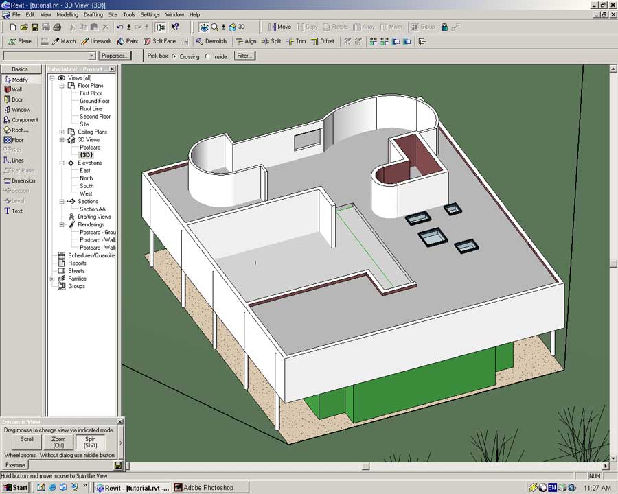
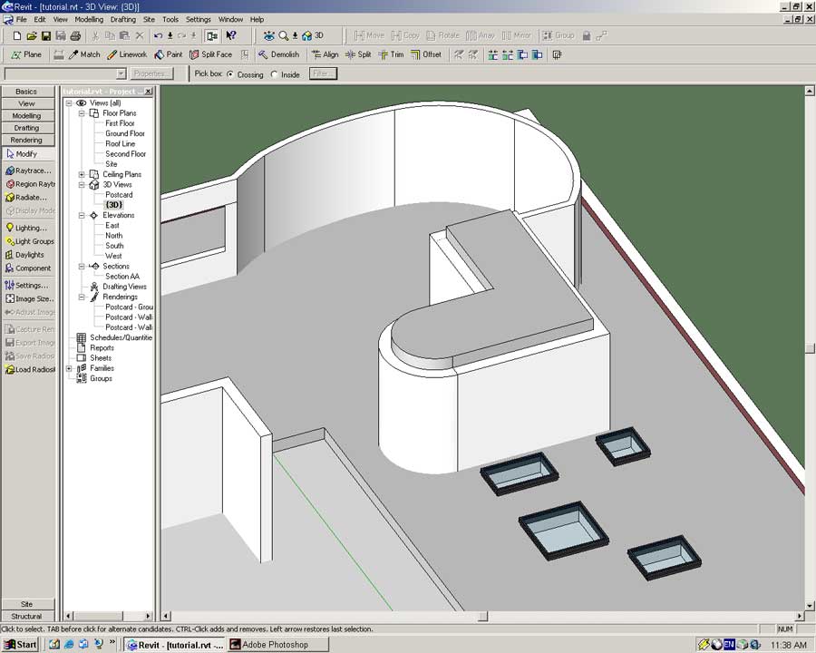
Open the {3D} view to examine the new opening.
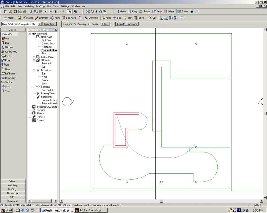
Open the Second Floor view. Hide the Roof and enable Raster Images from the View Properties.
Using the Lines tool trace around the outside edge of all the rooftop features.
Now is the time to play around with and get to know the Lines tool and its various options.
I will not help you too much; you will be on your own for a while.
To get you on your way I will give you a hand in defining the stairwell arc.
Using the Lines tool select the Arc with Centerpoint option.
Click in the center of the stairwell. Do not be too worried whether it is really the center or not, we can always move it later. Now create an arc by specifying a start and end points.
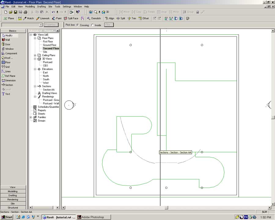
That is all the help I am going to give you. Keep trying until you have something similar to what is below. Notice I have hidden the Raster Images and Gridlines for clarity.
With that out of the way we will create another height plane to help build the structures on the roof.
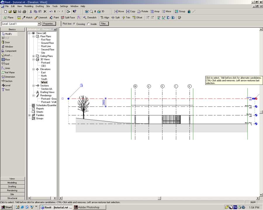
Open the North Elevation view.
Place a new Level 2800mm above the Second Floor named Roofline.
Open the Second Floor View.
Select the Wall tool from the Basics or Modeling Sidebar. Set the following properties:
Type: Basic Wall: Villa Savoye First Floor
On Level: Second Floor
Height: Roofline
Location Line: Finish Face Exterior
Place walls on along all of the lines around the stairwell. Remember to correctly align the wall's exterior face!
Use the Arc with Centerpoint option to complete the stairwell.
Select the Wall tool and set the following properties:
Location Line: Finish Face: Interior
Base Constraint: First Floor
Top Constraint: Second Floor
Top Offset: 500
Place walls in the places shown below. Ensure these walls are orientated correctly.
Now we are getting somewhere!
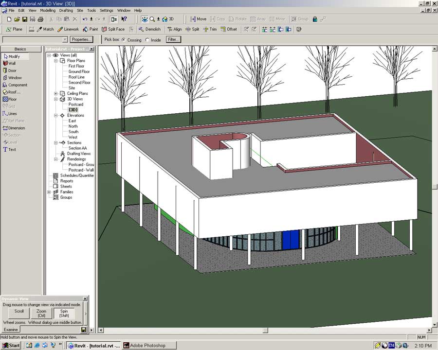
Open the {3D} and ensure all the walls are in the right place and orientated correctly.
The structure on the roof is of a lighter weight than the Villa's main walls.
Go back to the Second Floor view.
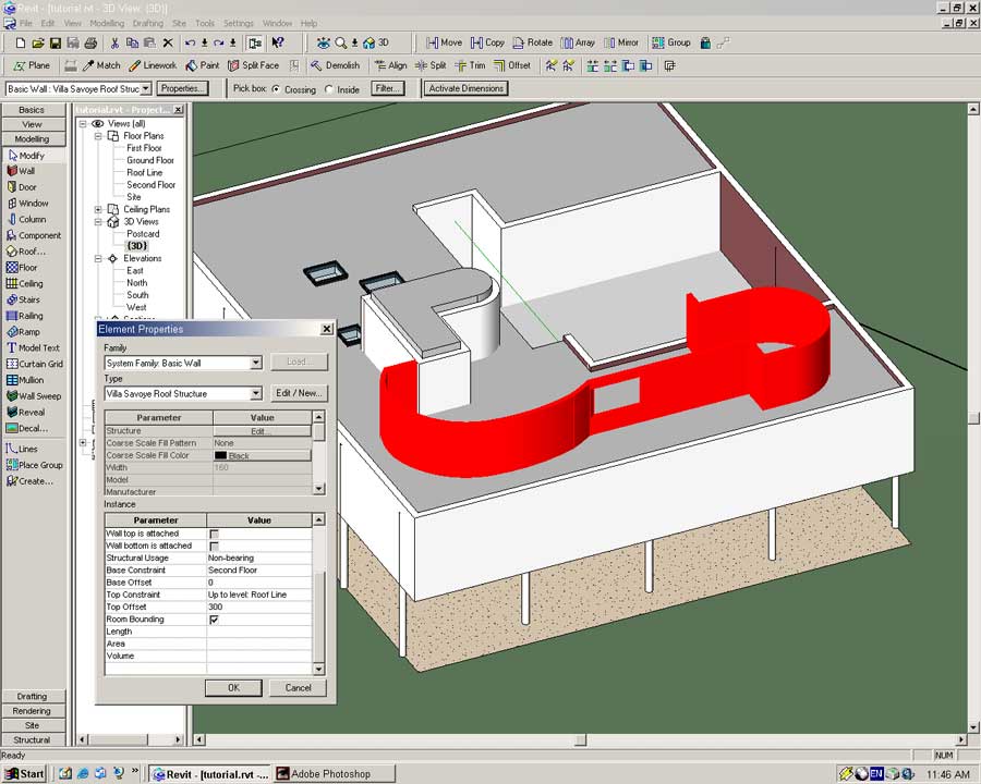
Select the Wall tool and press Properties.
In the dialog press Edit/New -> Duplicate
Name: Villa Savoye Roof Structure (Enter)
Edit the Structure of the wall to be similar to the example below.
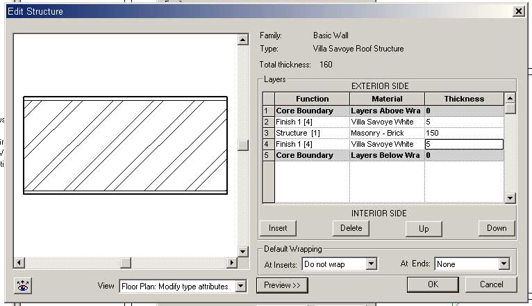
Press OK twice to create the new Wall object definition.
Set the Location Line to Finish Face: Exterior.
Place walls along the rest of the traced lines.
I am leaving you to your own devices here. Do not panic and take your time. Ensure the walls are orientated correctly to avoid any nasty surprises. Hopefully you should be able to construct something similar to what is pictured below.
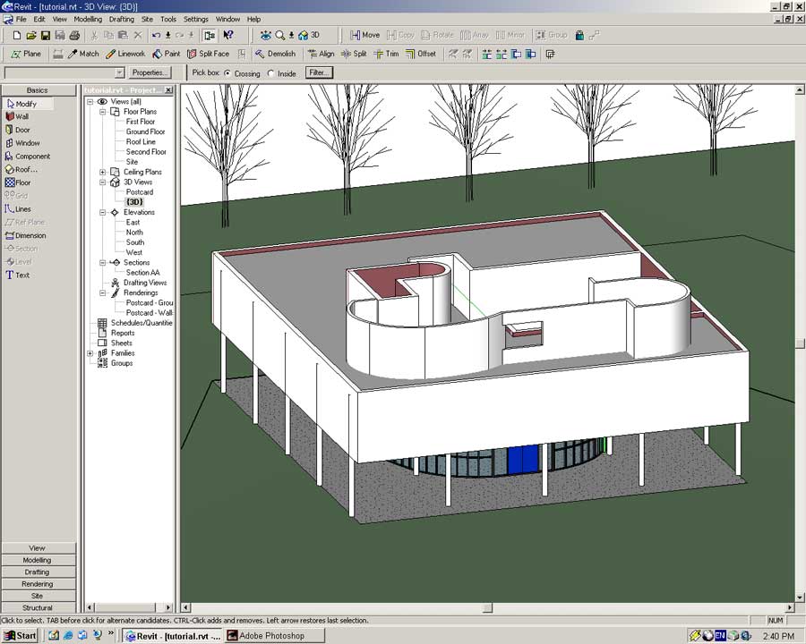
Open the {3D} view. With some luck we will both have the same thing.
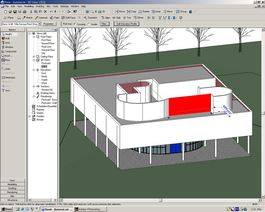
The highlighted wall in the screenshot above has a void taken out of it in the real Villa. We will achieve this by editing the wall's elevation profile.
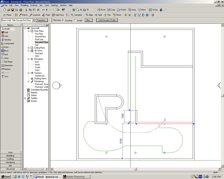
In the {3D} view select the wall and press the Edit Elevation Profile button.
Select the Lines tool from the Sidebar and enable chains.
Begin a line 1000mm up from the bottom-left point.
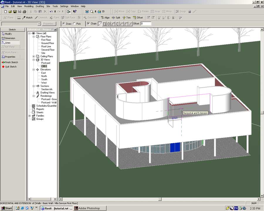
Place the next line 2000mm to the right.
Create a rectangular shape with the same dimensions as below.
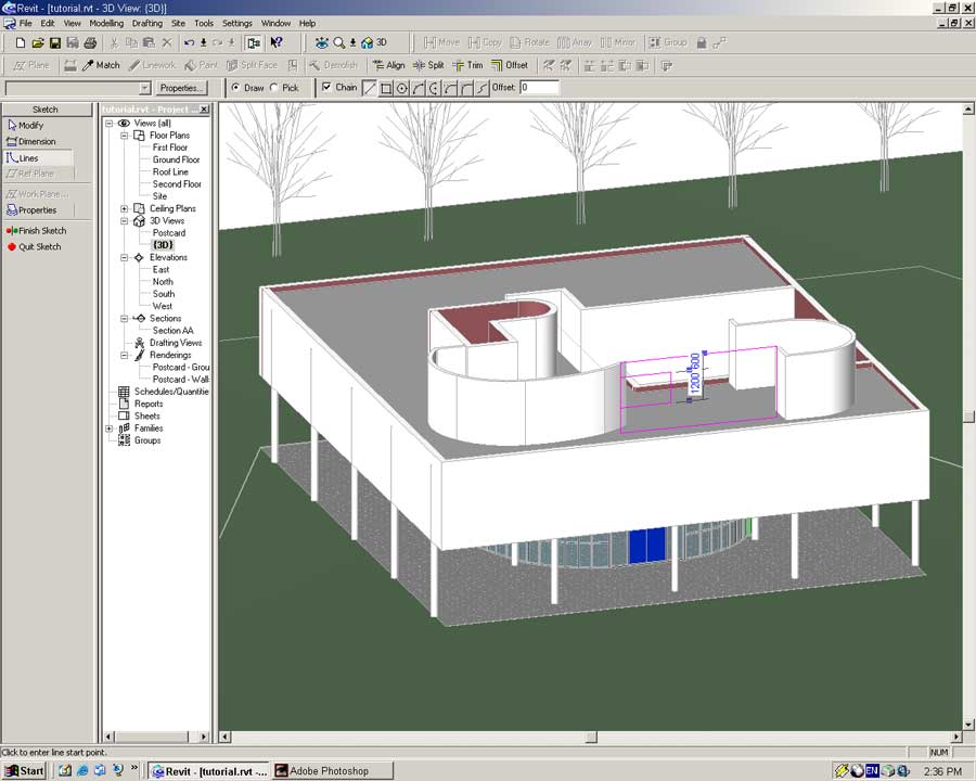
Using the Modify tool select the left hand line and delete it.
Using the line tool again complete the profile as shown below.
Press the Finish Sketch button in the Sidebar. A hole should be formed in the Wall element.
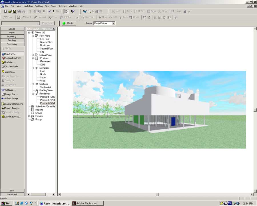
Open the Postcard view and create a raytraced image.
The tell tale image of the Villa Savoye is beginning to materialize.
Extra for Experts: Skylights Galore
This section is extra for those who like to suffer. If you are getting tired please move on to the next section Windows. The extra geometry we make here will not effect the model in later sections.
To light internal areas the Villa has several skylights in the roof.
Open the Second Floor view. Enable the Raster Image and hide the Roof objects in the View Properties dialog.
Place small Reference Planes on the bottom and right-hand edges of all the skylights in the image.
Once this is complete hide the Raster Image and make visible the Roof.
To place skylights into a model the Skylight family must be loaded.
From the menu select -> File -> Load from Library -> Load Family...
Browse to the Metric Library/Windows directory and open the M_Skylight.rfa file.
The Skylight is a unique window object as it forms a relationship with the Roof object (other Window objects are related to the Wall object).
In order to size the skylights correctly we will create custom objects based on the basic Skylight object.
Use the Tape Measure tool to determine the size of the first skylight.
From the menu select -> Tools -> Tape Measure
Measuring with the tape measure is easy; just click on two points.
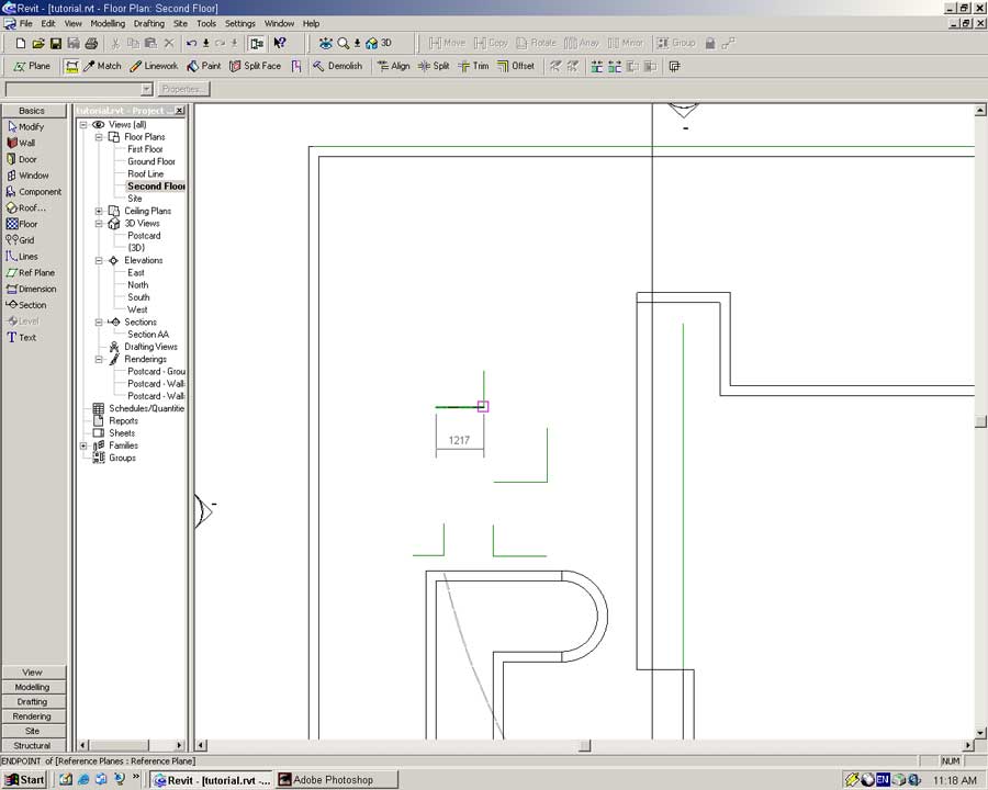
The dimensions of my first skylight is 937 x 1217 (Don't worry if your measurements are different).
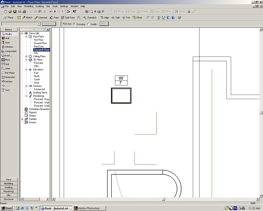
Select the Window tool from the Sidebar and press the Properties button.
In the dialog set Family to Skylight and press Edit/New -> Duplicate
Name: Villa Savoye Skylight 1 (Enter)
Width: 1217
Height: 937
Press OK in all the dialogs to create the new object definition.
The new object M_Skylight: Villa Savoye Skylight 1 will be selected in the Type field of the Window tool.
Move the pointer to the intersection of the two Reference Planes and place the skylight.
Repeat the process for the other skylights.
To complete the roof structure we need to place a roof on the stairwell.
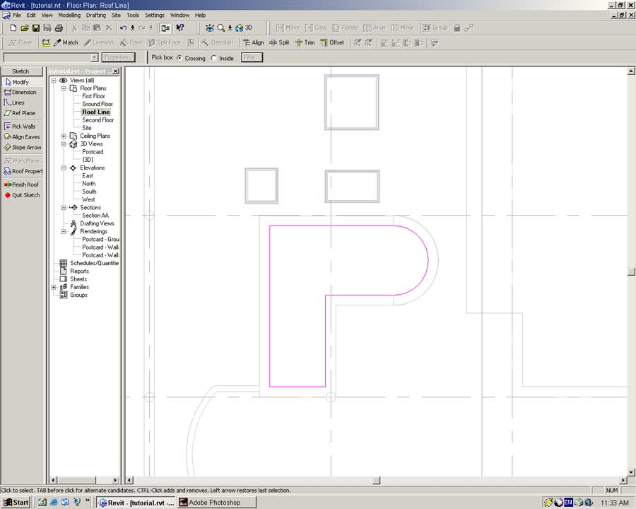
Open the Roofline view.
In Basics or Modeling Sidebar select the Roof tool and choose to define a Roof by Footprint.
Select the interior surfaces of the stairwell for the roof profile and turn off any slope definitions as shown below.
Set the roof type to Cold Roof Concrete and build.
Open the {3D} view, you should have the following:
This is not what we want! Unfortunately for us roves cannot be constructed below a Level (else they could be considered floors). We have two solutions to this dilemma.
a) Create a Floor Slab object instead of a Roof object.
b) Move the Roofline Level down and offset the wall height.
Either option will achieve the same result but (a) does not follow object-modeling principles. What we are modeling is a roof, so it should be modeled using a roof object else we loose the power of the object-orientated approach.
We will move the roof level down 300mm and offset the walls by this same amount.
Open the East Elevation.
Select the Roofline Level and press the Properties button.
Set the Elevation to 8500 and press OK.
And like magic the roof and walls are lowered.
Open the {3D} view and select the 'Villa Savoye Roof Structure' wall elements.
Open the Property dialog for these objects and set their Top Offset value to 300.
Repeat the process for the thicker walls on the Second Floor level.