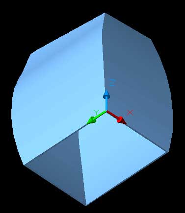
Now that the solid is made we can now carve away an interior. AutoCAD has a shell command that will let us quickly create a shell of a solid a specified thickness.
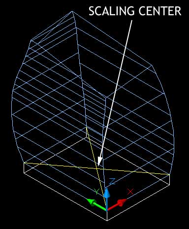
Find the center point at the base of the solid to act as a base point for scaling. using the center point for scaling ensures that all points are scaled evenly inwards. If the scale point is not in the center the resulting scaled object will not be the same as the original object.
18. Create two intersecting lines at the base of the newly created volume.
Turn the foundation layer on so that it is visible.
Change layer to construction.
Change UCS to world.
Select the line tool or
Type: line (Press Enter)
Specify first point:
Click on one of the top corners of the foundation.
Specify next point or [Undo]:
Click on the opposite top corner.
(Press Enter)
Repeat for the other two corners.
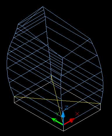
Two lines should be created in the construction layer like the image below.
19. Create a copy of the solid and scale to smaller size.
Turn on the walls layer.
Make the walls layer the current layer.
Type: copy (Press Enter)
Select objects:
Select the solid shape (Press Enter)
Specify base point or displacement, or [Multiple]:
Click anywhere (preferably on a point)
Specify second point of displacement or <use first point as displacement>:
(Press Enter) To use first point.
A copy of the solid is made in the same location as the first.
20. Now scale the copied shape.
Type: scale (Press Enter)
Select objects:
Select one of the solids (Press Enter)
Specify base point:
Click on the point where the two construction lines you created above intersect. Make sure the point has a yellow cross at the intersection point. With the object snap turned on the intersection between the two lines will be selected.
Specify scale factor or [Reference]:
Type: 0.964 (Press Enter)
The solid will be scaled down by a factor of 0.964
Where did 0.964 come from?
In order to get a wall thickness of 250 the original object 14000 wide needs to be scaled by approximately 0.964 to create a scaled size of 13500. Remember back to sixth form maths if you are not sure how this number is achieved.
For those of you who failed sixth form maths divide 13500 by 14000 to get 0.964......
You should with a little luck have two solids, one slightly smaller than the first.
If we were to subtract the inner solid from the outer solid now the bottom of the shape would not be removed from the resulting solid. It would have a solid exterior but a hollow interior, like an easter egg.
To get around this little inconvenience we will move the interior solid down 1 unit in the z direction.
21. Ensure the UCS is set to world.
Type: move (Press Enter)
Select objects:
Select the interior solid (Press Enter)
Specifiy base point or displacement:
Click anywhere, preferably on a point.
Specify second point of displacement or <use first point as displacement>:
Type: @0,0,-1 (Press Enter)
The shape will move down 1 unit. You will not notice anything but it makes all the difference.
23. Subtract the inner solid from the outer solid.
Ensure that your current layer is the walls layer.
Type: subtract (Press Enter)
Select objects:
Select the larger solid (Press Enter)
Select objects:
Select the smaller solid (Press Enter)
The interior of the solid will be cut away leaving a hollow shell.
NOTE: in recent years the Solidedits too bar and command set within AutoCAD has included a 'shell' command that will make a solid into a thin shell at a single command. However, like most CAD shell commands it has problems as objects become more complex and so the vertices (corners) become harder to resolve. This appears to be a problem with this solid. Hence our old-fashioned approach to this part of the modelling.
Shade the view and move around the views to check your creation.