Before extruding the polylines they need to be moved backwards so that they intersect completely.
13. Move the first wall backwards:
Switch to the Southwest Isometric view:
->Views ->3D Views ->SW Isometric
Change the UCS to world
Type: ucs (Press Enter)
Type: w (Press Enter)
Ensure Ortho Projection is on. If you are not sure press F8. A text message will say whether it is off or on.
Type: move (Press Enter)
Select object:
Click on the first smooth polyline created (Press Enter)
Specify base point or displacement:
Click on a corner point as shown in the below image.
Specify second point of displacement:
drag the cursor backwards
Type: 5000 (Press Enter) 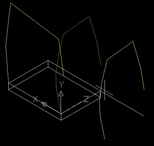
Repeat this process for the second wall.
14. Extruding the two shapes.
Finally it is time to make a solid shape. To do so we will use the "extrude" tool. The extrude tool creates a 3-dimensional solid from a 2-dimensional cross-section and a path. For this exercise we will just do a simple straight extrusion. Straight extrusions occur along the z-axis and your 2-dimensional cross-section should be aligned with the x and y axis of the current UCS.
To use the extrude tool the cross-section must be a closed path, in other words it cannot have any gaps or breaks in the curve. The two polyline cross-sections that have been created fit this scenario.
Change the UCS to match the orientation of your first polyline shape (front elevation).
From the menu select:
->Tools ->Named UCS..
A dialog box will appear.
Click on the UCS you wish to use (front elevation) and press 'Set Current'.
Change your current layer to walls.
Type: extrude (Press Enter)
Select objects:
Select the first shape (Press Enter)
Specify height of extrusion or [Path]:
Type: -30000 (Press Enter)
Specify angle of taper for extrusion [0]:
(Press Enter)
A new 3-dimensional shape should be created as shown below. (Note the UCS) 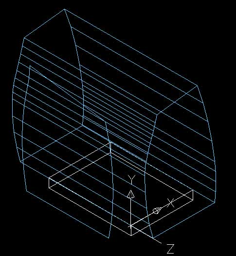
Your end result should look like the image below. 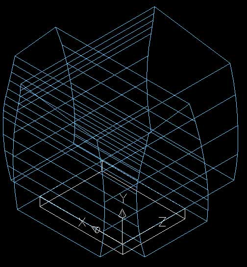
To check the correct placement of the solids switch to a number of views or use the orbit command to view your object from any angle.
15. Create volume based on intersection.
Type: intersect (Press Enter)
Select objects:
Select the two volumes (Press Enter)
If everything goes to plan (which with my experience with computers it usually does not) you should have a single solid curved shape like the one below.
Shade the drawing window by selecting:
->View ->Shade -> Gouraud Shaded (or any other type of shading)
or
Type: shade (Press Enter)
All that is left to do to create the exterior form is cut away the roof a little to give it its sloping nature.
To do so we will use the slice tool. The most difficult step in this process is finding the correct starting point for the slice.
16. Find starting point for slice.
Change current layer to construction.
Change the UCS to world.
Change to the South West Isometric View.
Type: line (Press Enter)
Specify first point:
Type: 0,0,0 (Press Enter) which is also referred to as point A. (refer to below image or previous images).
Specify next point or [Undo]:
Type: @0,0,21310 (Press Enter)
(Press Enter) (To finish drawing the line.)
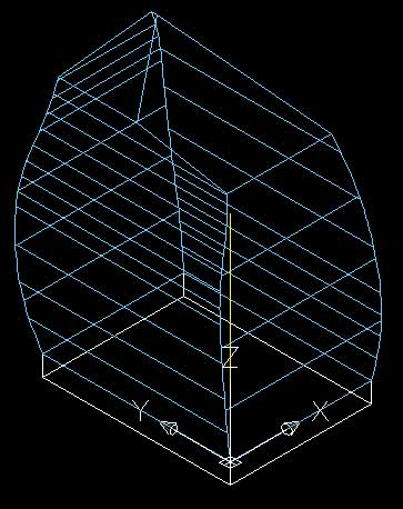
A line will be created from the base of the object to a point 90% of the way up the volume as shown on the below image. This is the first point of your slicing plane.
Why did we use the line tool and not the polyline tool this time?
Good question. The polyline tool is more versitile than the line tool as it can be extruded and easily modified but it can only operate in two-dimensions. The polyline does not accept 3-dimensional co-ordinates like the one above as it only operates in the x and y axis. To do the same operation using a polyline we would have to rotate the UCS to an angle of about 85o so that the operation would become two-dimensional.
If you do not understand the above do not start to panic. Just remember that polylines only work in two-dimensions.
17. Now slice off the top of the roof.
Change the current layer to walls.
Type: slice (Press Enter) or from the menu select:
Draw -> Solids -> Slice
Select objects:
Select the wall solid (Press Enter)
Specify first point on slicing plane by [Object/ZAxis/View/XY/YZ/ZX/3points] <3points>:
(Press Enter) (This selects the default option of three points.)
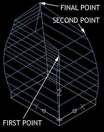
Click on the three points shown in the above image in the order described. The points are all located at the very top of the shape.
Make sure the object snap is turned on and the selection box turns yellow when holding the pointer over the desired point. This is AutoCAD's way of telling you it has found the end-point.
Specify a point on desired side of the plane or [keep Both sides]:
Click on the lower corner of the main volume
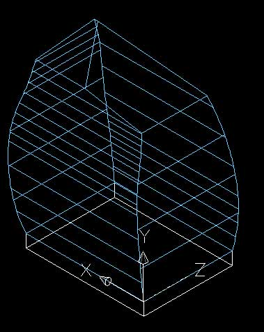
This action creates a slicing plane. The slicing plane creates a new shape with a slice missing.
If you appear to have two shapes, an original and a sliced solid select the larger original and Press Delete.
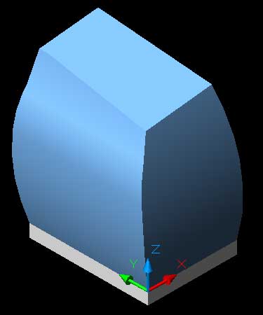
Your completed shaded shape should look like the image below.
If your shape is wildly different you may have typed an incorrect co-ordinate. To undo a step in AutoCAD select from the menu:
->Edit ->Undo
or
Type: undo (Press Enter)
Enter the number of operations to undo or [Auto/Control/BEgin/End/Mark/Back] <1>:
Type: (The number of steps you wish to go back eg. 5) (Press Enter)
or
Press Ctrl and Z at the same time.
You will notice that the roof is flat when in reality is has a lowered area with a ledge. We will not create the lowered area in this tutorial but if you are feeling up to it you could give it a try. The roof is lowered butress like the one shown below.
