The curved exterior form of Frank Gehry's design is a very challenging piece for any 3-dimensional computer designer. If you can successfully create this form then it is possible to create anything in your model.
This section has been divided up into three sections to ease navigation.Although this method is long the concept behind it is fairly simple. Once you have a grasp of AutoCAD many of these operations become second nature. In other words do not worry if you are at first confused. If this was swimming you would be definitely be in the deep-end. Take heart, if you master this tutorial your assignment will be a walk in the park, (as long as you do not model Frank Gehry's Guggenheim...).
6. Change the view point to front by going up to the menu bar to:
->View ->3D views ->SW Isometric
Now change the UCS to a vertical front elevation:
Type: ucs (Press Enter)
New/Move/orthographic/Pre/Restore/Save/Del/Apply/?/World:
Type: x (Press Enter)
Specify rotation angle about x axis <90>:
Type: 90 (Press Enter)
The UCS pointer will now change. You will notice the x-y UCS will now be vertical rather than horizontal.
Save the current UCS so that you do not have to continually go through this process.
Type: ucs (Press Enter)
Type: save (Press Enter)
Now give the UCS a name.
Type: front elevation (Press Enter)
7. Change to the layer called "construction".
Click on the layer drop-down list and then select the layer titled construction.
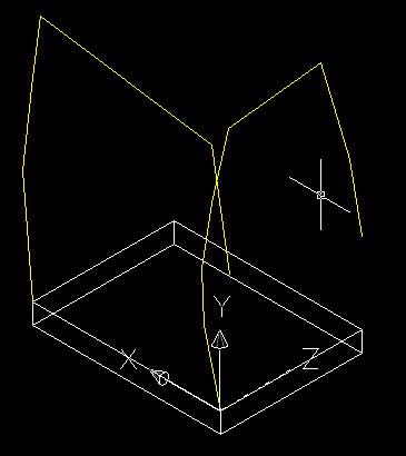
The following process creates a two dimensional formwork for the three dimensional shape. These two dimensional shapes are turned into solids. The area where these two solids intersect becomes the final shape.
DO NOT PANIC if you do not understand this process initially.
By following the instructions through to the end result things should become clearer. You can use this technique to create any volume imaginable.
The images below are of the drawing process. The cube you have created is represented in these images by a rectangle with four points. The four points on the rectangle are the four top corner points on the foundation cube.
Click on an image to enlarge. They have been made smaller for this page to reduce the amount of scrolling and downloading that must occur.
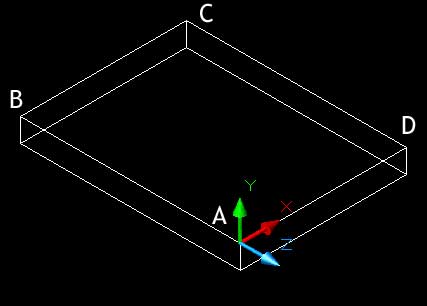
8. Click on the bottom right corner marked A (0,0,0) in the above image.
Note the direction of the UCS x and y axis if you are unsure.
Type: pline (Press Enter) or select the polyline tool.
Specify start point:
Click on corner A
Specify next point:
Type: @-1645, 8170 (Press Enter)
Type: @-200,5000 (Press Enter)
Type: @1000,5100 (Press Enter)
Type: @1675,5500 (Press Enter)
Type: @9170,1050 (Press Enter)
Type: @2800,-9650 (Press Enter)
Type: @1200,-7170 (Press Enter)
(Press Enter)
This sets up the formwork for the frontal elevation.
Switch to the front elevation to view the formwork: Select from the menu:
->View ->3D View ->Front
Your drawing should look like the images below: 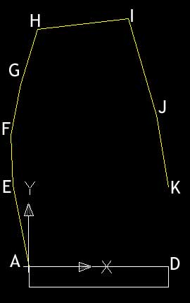
9. Change to the wall layer.
The next polyline will be a continuous curved polyline that flows along the points found by the formwork.
Type: pline (Press Enter)
start point:
Click on point A
Type: arc (Press Enter)
Type: sec (Press Enter)
Click on points E, F, G and H
Type: line (Press Enter)
Click on I
Type: arc (Press Enter)
Type: sec (Press Enter)
Click on Points J,K and D
Type: line (Press Enter)
Type: close (Press Enter)
You should now (fingers crossed) have a single polyline shape that smoothly follows the formwork.
Now it is time to create the side elevation.
10. Switch to the SW Isometric view and change the current layer to construction. You should know how to do this but if you are unsure take a look at step 7.
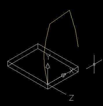
We will rotate the UCS 90o about the y-axis to draw the side elevation.
Command:
Type: ucs (Press Enter)
Type: y (Press Enter)
Type: 90 (Press Enter)
command :
Type: ucs (Press Enter)
New/Move/orthographic/Pre/Restore/Save/Del/Apply/?/World:
Type: save (Press Enter)
name the ucs:
Type: side elevation (Press Enter)
Note, you could align a UCS to a face by typing <face> as the option immediately after ucs and <enter>. This will ask you to point to the face of a solid object that you wish to align the UCS with. The next command allows you to step through the faces of the object until you find and confirm with the enter key which one you want to select. Once you have selected the face you will still have options to flip about the X or Y axis if the ucs is aligned but, say, upside down.
Your new UCS should look like this: 
To change your current UCS from the menu select:
->Tools ->Named UCS..
This will bring up a dialog box like the one below: 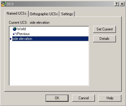
Select the UCS you want and press the Set Current button.
For this we need the side elevation.
11. Draw the new construction formwork.
Change to the left view. From the menu select:
->View ->3D Views ->Left
NOTE: Often when you click a preset view option like this AutoCAD loads a preset UCS as well. Be sure that the UCS is oriented with positive X direction from point A to point B. If not then after setting up the left view, reselect the appropriate UCS you saved earlier.
Command:
Type: pline (Press Enter)
Select first point:
Click on point B (The left most point at the top of the foundation.
Select 2nd point:
Type: @980,10850 (Press Enter)
Type: @-1000,8500 (Press Enter)
Type: @-770,5550 (Press Enter)
Type: @-17000,-2480 (Press Enter)
Type: @-1700,-10200 (Press Enter)
(Press Enter)
Your formwork should look like the images below:
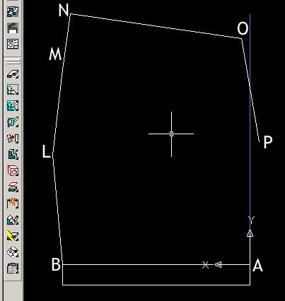
The same process of creating a single smooth line must be repeated for the new formwork.
12. Change to the walls layer.
Command:
Type: pline (Press Enter)
Click on point B
Type: arc (Press Enter)
Type: sec (Press Enter)
Click on points L, M and N
Type: line (Press Enter)
Click on point O
Type: arc (Press Enter)
Type: sec (Press Enter)
Click on points P and A
Type: line (Press Enter)
Type: close (Press Enter)
The side elevation will now be created.