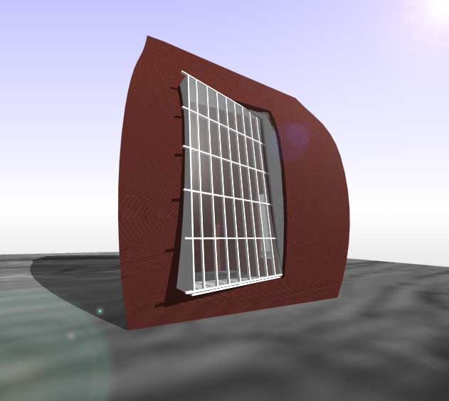
The completed main window rendered in AutoCAD with a few materials and a tacky lens flare Photoshop effect thrown in for good measure.
(Yes I know the lens flare and the shadow do not match up...)
Setting Up Different Viewports
Using the Dview Command to Set View
Using the Architectural Desktop Camera Tool
Saving the Created View
Rendering in AutoCAD
This section deals with the setting up of your drawing windows and creating 3-dimensional views of your model. I will not go into great detail into how each view can be created as setting your own views in AutoCAD is a process of experimentation and error.
My only advice is to be patient and be prepared to start over when searching for the right view.
Views set up in AutoCAD can be saved and exported into Lightscape and Radiance. New views can be defined in Lightscape but although it is possible to do the same in Radiance it is usually best to set your view in AutoCAD and export it in.
Setting Up Different Viewports
A helpful feature of AutoCAD when setting up views is the ability to create different windows on your screen containing the same drawing.
Select from the menu:
->Views ->Viewports
Select any of the options shown.
A different combination of viewing windows are set up on your drawing window. To return to the default setup select 1 Viewport.
To activate a drawing window click on it once. Once this is done the window acts as any normal drawing window.
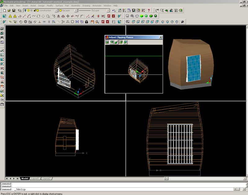
It is possible to view perspective, elevation and plan at the same time. This is most useful for discovering where things are in 3-dimensions.
An example of the possibilities provided are shown below.
Using the DView Command to Set View
(for reference only - see text below for Architectural Desktop Camera Setup
The DView command is a very old feature of AutoCAD that is either loathed or hated, (usually loathed). It has been replaced mostly by the Orbit tool but it still has its uses.
Its primary advantage is its ability to set a target and a camera location and create the view.
Switch to the SW Isometric View
Make the construction layer active.
Set the current UCS to world.
Set the shading to 2-Dimensional Wireframe.
Draw a line from the left corner of the building to a point in space.
Type: line (Press Enter)
Click a place where you would like to view the building from.
Type: @0,0,1800 (Press Enter)
Type: dview (Press Enter)
Select objects:
Type: all (Press Enter)
(Press Enter)
[CAmera/TArget/Distance/POints/PAn/Zoom/TWist/CLip/Hide/Off/Undo]:
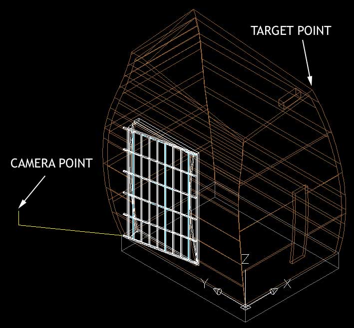
Type: points (Press Enter)
Select the target and camera points.
A new view will be generated in the drawing window. It will not look like the view you thought you would get. Do not worry.
Use the distance tool to move towards the model.
Type: distance (Press Enter)
Move the mouse left and right. The model will get closer or further away.
Click the left mouse button once the model is the distance you want it.
The default field of view is very small. Use the zoom tool to extend your field of view.
Type: zoom (Press Enter)
Move the mouse left or right to zoom in and out.
Click the left mouse button once the model is zoomed correctly.
(Press Enter) to set the view.
NOTE: If you do not press enter to set the view it will return to the Front Left Isometric viewpoint. This happens if you press the Escape key.
A brief desciption of the dview commands:
Camera: Sets the location of the camera.
Target: Sets the target point.
Distance: Sets the distance from the camera the viewer is standing. (Thats how I think of it anyway.)
Point: Sets two points in space for the camera and target.
Pan: Pans the view left or right. The target does not change.
Zoom: Zooms in and out- changes your field of view.
Twist: Twists the camera on its axis.
Clip: Replaced by the Clipping Plane window. Creates a cutting plane that allows for cross-sectional drawings.
Hide: Produces a hidden wireframe view of the drawing window. Any lines that the user cannot see from their camera location are hidden.
Off: Turns any of the above options off.
Undo: Undoes the last dview command.
Using the Architectural Desktop Camera Command to Set View
The DView command is now pretty much made obsolete.
Set up two viewports looking at your model.
Select <Documentation><Perspectives><Add Camera...> from the pull down menus.
A menu will pop up with settings for camera lens size, height above the XY Plane (you might want to make sure the UCS coordinates are set to the world coordinates at this point) and name. For the present IGNORE THIS popup menu. Note in the command line you are being asked to place the camera. Click on the position on the XY plane where you wish to be standing and you will find a 3D triangular view from the camera position is dragging alonside your pointer/cursor. Click on the building where you want to be looking (the camera "target" in AutoCAD parlance). Now you are being prompted to "Pick viewport to generate perspective in". Pick the other viewport with you mouse. Now you will find that you can move the camera about and alter the view in this viewport either by click and drag or by going back to the <Documentation><Perspectives><Adjust Camera View> menu.
Note: you can use these menus to create small animations, wide angle (fish eye) effects, and all sorts of other interesting views of your building. When you have used this menu, you will find that there is no need to save views because the camera names are found in the saved view window.
Saving the Created View
To save the view select from the menu:
->Views ->Named Views...
The dialog box below will appear.
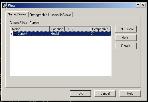
Select the Named Views tab.
Press the New button.
Type a name for your view
(Press Enter)
Your current view will be saved.
To load a view double click on the view you want or select the view and press the Set Current button.
Create a number of diffferent views in AutoCAD. Experiment with different internal and external views.
Rendering in AutoCAD
To do a quick render follow the steps below.
Increase the accuracy of the rendered model.
From the menu select:
->Tools ->Options...
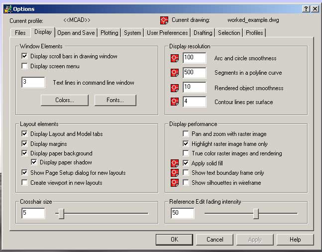
From the dialog box select the Display Tab
In the Rendered Object Smoothness box change the value to 10.
This creates a smooth rendered object.
Click the OK button.
Type: render (Press Enter)
Play around with any of the rendering options.
NOTE: The more options you select the slower the render.
Use the Help option to find out what each option does.
Once you have selected the options you desire press the Render button.
In AutoCAD you can assign materials and lighting. To do so check out the help files on the subjects.
To open the Materials and Lighting dialog boxes get access to them through the:
View -> Render menu.
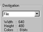
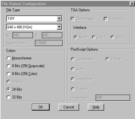
To save a rendered image, select the file option in the Destination dialogue in the render dialogue. Now when you render the program wants to know what file name (and place on the disk - it would make sense to use your I:\drive) you want to save under. You should also select the More Options button and set the render output file type to TIFF and the number of colours to 24 bit and the size (number of pixels or dots) of the image.
To place this image into a web page, you will need to load the TIFF file into Photoshop or some equivalent and save it as a jpeg file (name.jpg).
You can also save an interactive image (what autodesk term an e-plot) by selecting the e-plot output switches and creating a name.dwf file. This will be linked in your web page as usual. The image that is loaded in the web browser can be viewed on the School's machines (where the correct plug in has been loaded onto our web browsers). If you have saved some named views in AutoCAD or have a set of named layers, then those people with the viewer plug in installed in their browsers will be able to look at each view, to zoom and pan the image and to turn layers on and off.
Conclusion
You have hopefully got through this tutorial without too much trouble and have learnt a little about AutoCAD and Architectural Desktop 3.
AutoCAD is a huge programme with many options and tools that cannot be possibly covered in one tutorial, utilise the online help and other tutorials alongside simple experimentation to gain a good understanding of the inner workings of AutoCAD.