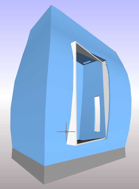
The main window is made up of straight, perpendicular elements that contrast with the curved nature of the exterior form. The window is also set on an angle to the general axis of the space.
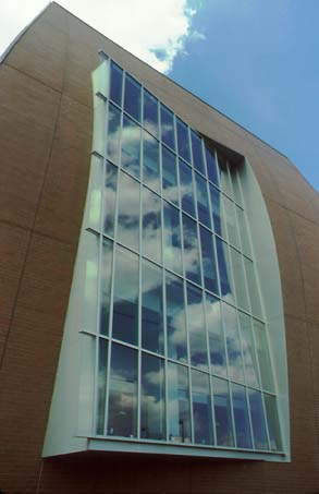
The main window section is broken into two parts.
We will first create the window enclosure. This enclosure acts as an intermediate form between the curves of the wall and the straight lines of the window.
The first step is to re-create the curve of the exterior wall using the same method as was used in "Step 4. Curved Form" - Sections 9 and 10.
29. Change the current view to the SW Isometric View
Restore the "front elevation" UCS.
Type: ucs (Press Enter)
Enter an option [New/Move/orthoGraphic/Prev/Restore/Save/Del/Apply/?/World] <World>:
Type: r (Press Enter)
Enter name of UCS to restore or [?]:
Type: front elevation (Press Enter)
or bring up the UCS dialog box by selecting from the menu:
->Tools ->Named UCS...
Select the UCS you require and click Make Current.
Change to the construction layer.
NOTE: You will not be requiring any of your construction lines created up to this point. You can delete them if you wish or hold onto them. A safe option would be to set up a new construction layer for making the main window and keep the other construction layer. This way if something goes wrong you can always go back to the construction lines and start over.
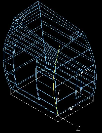
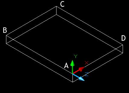
30. We will only recreate the curve we need. Use the naming conventions and images from "Step 4 Curved Form".
Click on the bottom right corner marked A (0,0,0) in the above image.
Note the direction of the UCS x and y axis if you are unsure.
Type: pline (Press Enter) or select the polyline drawing tool.
Specify start point:
Click on corner A
Specify next point:
Type: @-1645, 8170 (Press Enter)
Type: @-200,5000 (Press Enter)
Type: @1000,5100 (Press Enter)
Type: @1675,5500 (Press Enter)
(Press Enter)
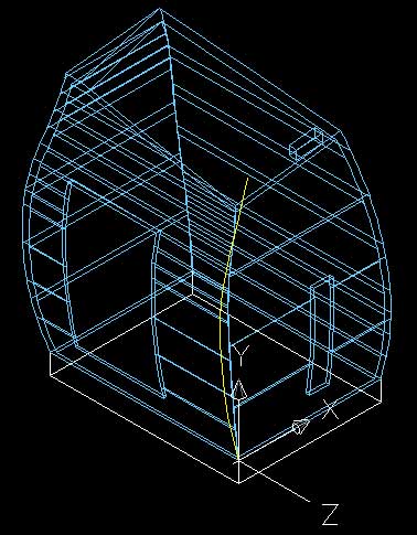
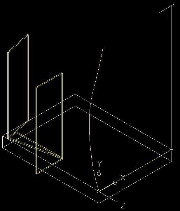
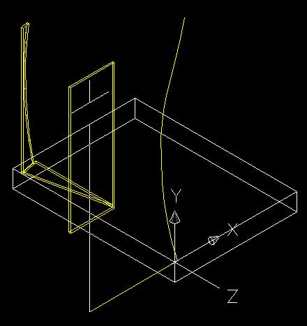
31. The next polyline will be the continuous curved polyline that flows along the points found by the formwork.
Type: pline (Press Enter)
start point:
Click on point A
Type: arc (Press Enter)
Type: sec (Press Enter)
Click on points E, F, G and H
(Press Enter)
We will set this line aside for the moment whilst we construct the box for the window.
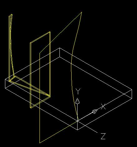
32. To simplify life we will create a new UCS that is aligned with the axis of the main window.
Type: ucs (Press Enter)
Enter an option [New/Move/orthoGraphic/Prev/Restore/Save/Del/Apply/?/World] <World>:
Type: w (Press Enter)
Type: ucs (Press Enter)
Enter an option [New/Move/orthoGraphic/Prev/Restore/Save/Del/Apply/?/World] <World>:
Type: z (Press Enter)
Specify rotation angle about Z axis <90>:
Type: 12 (Press Enter)

Type: ucs (Press Enter)
Enter an option [New/Move/orthoGraphic/Prev/Restore/Save/Del/Apply/?/World] <World>:
Type: origin (Press Enter)
Specify new origin point <0,0,0>:
Click on the point marked in the image below.
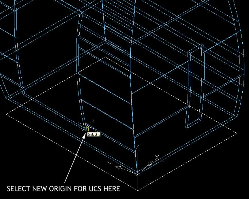
The origin point of the UCS, (point 0,0,0) will move the point where you selected.
34. Save this new UCS as "window plan" (as the x and y axis is horizontal).
Type: ucs (Press Enter)
Enter an option [New/Move/orthoGraphic/Prev/Restore/Save/Del/Apply/?/World] <World>:
Type: s (Press Enter)
Enter name to save current UCS or [?]:
Type: window plan (Press Enter)
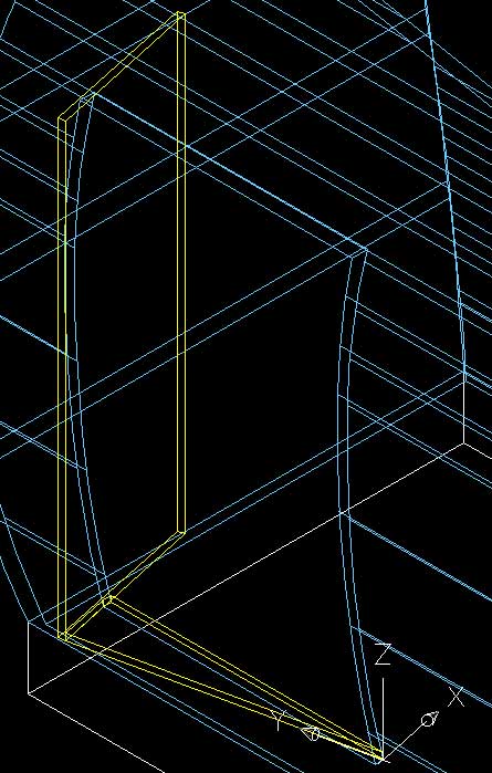
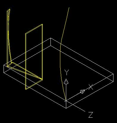
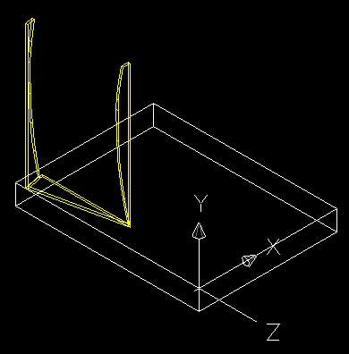
35. Create the base of the window.
Ensure ORTHOGRAPHIC mode is turned on.
Type: pline (Press Enter) or select the polyline tool.
Type: 0,0,0 (Press Enter) or click on the new origin point
Specify next point or [Arc/Halfwidth/Length/Undo/Width]:
Drag the line to the left of the drawing window. A line running parallel with the y-axis of the ucs should be created.
Drag the line out any distance you like, (as long as it is longer than the window) and click the left mouse button to define the end point.
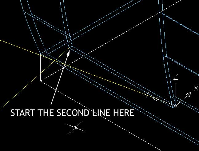
Repeat the process but start the new polyline at the point shown below and drag the new line down the drawing window as shown.
We will trim one of the intersecting lines and move the point of the other line to create the triangle shape.
36. Trim polyline in x-direction.
Type: trim (Press Enter)
Select objects:
Select the two newly created polylines.
(Press Enter)
Select object to trim or shift-select to extend or [Project/Edge/Undo]:
Select the polyline created second.
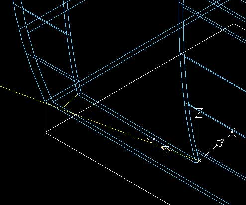
The polyline should be trimmed to the length of the intersection between the two lines. As shown below.
(Press Enter)
NOTE: We could of selected the second polyline and had it trimmed to the same length but for the process of this tutorial we will manually move the second polyline to the desired location.
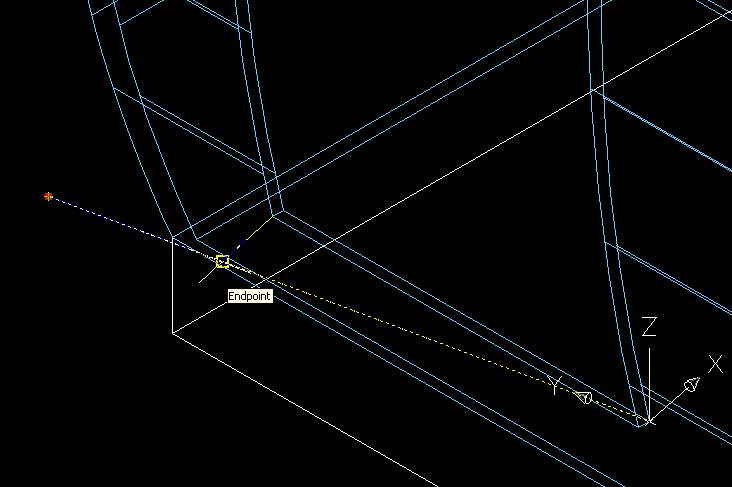
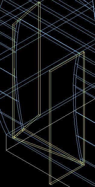
37. Move the point of the first polyline to the newly trimmed end-point of the second polyline.
A useful feature of 2 or 3-dimensional lines, shapes and surfaces in AutoCAD is their ability for the points that make up the shape be edited after creation. Unfortunately this rule does not apply to solids.
Select the first (long) polyline.
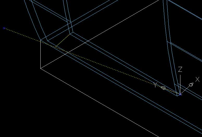
Its appearance will change from a solid to a dashed line and the two end-points will have blue boxes at either end, as shown in the image below.
Ensure that OBJECT SNAP is enabled.
The OSNAP button at the bottom of the drawing window should be pushed in.
Click on the leftmost point of the selected line.
The end-point of the line will be selected. The blue square will change to red.
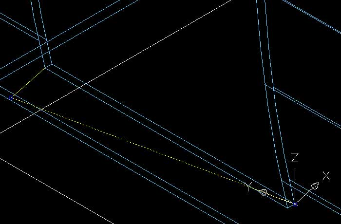
Move the cursor to over the end of the second polyline as shown below and click on it.
The polylines should now intersect at a point as in the image below.
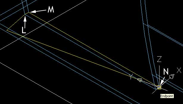
38. Create a a line to line the two ends together.
Type: line (Press Enter)
Select point L as a starting point.
Click on point M and then N.
(Press Enter)
A line will be made as in the image below.
Normal lines, like the one created in step 38 can be turned into a polyline as long as they run parallel to the current UCS (remembering that polylines only take x and y co-ordinates).
We will turn this line into a polyine and join it to the other polylines to make the shape for extrusion. This is all done with the polyline edit command. It is a very powerful tool that sets the polyline apart from a normal line.
39. Edit the newly created line to join the polylines into one polyline.
Turn off the wall layer to get a better look at the lines.
Type: pedit (Press Enter)
Select polyline or [Multiple]:
Select the normal line we have just created.
Object selected is not a polyline
Do you want to turn it into one? <y>
Type: y (Press Enter)
Enter an option [Close/Join/Width/Edit vertex/Fit/Spline/Decurve/Ltype gen/Undo]:
Type: join (Press Enter)
Select the two polylines and press enter.
Type: close (Press Enter)
(Press Enter) to exit.
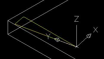
All three polylines will be joined into a single closed polyline.
Type: extrude (Press Enter)
Type: 200 (Press Enter)
(Press Enter)

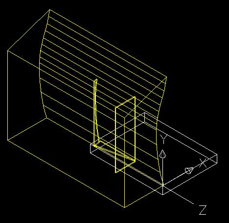
41. Turn the walls layer on to get an idea of the form.
Create a box from point 0 (shown on the image below).
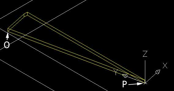
Type: box (Press Enter)
Select point O
Type: @5000,200 (Press Enter)
Type: 14450 (Press Enter)
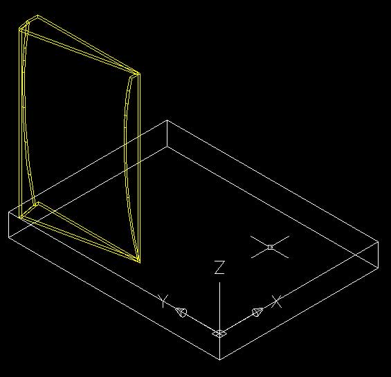
The first side panel will be created as illustrated below.
42. The second side panel runs parallel with the world UCS.
Change the UCS to world.
Type: ucs (Press Enter)
Type: w (Press Enter)
From point P (shown in the previous image) create a box.
Type: box (Press Enter)
Select point P.
Type: @-5000,-200 (Press Enter)
Type: 14450 (Press Enter)
Make a copy of the curve we created at the beginning of the section.
Type: copy (Press Enter)
Select the curve
(Press Enter)
Select any point
Type: @0,0,0 (Press Enter)
Switch to the front elevation ucs.
Create a polyline from origin, point A (0,0,0).Ensure that OSNAP and ORTHO modes are on.
Type: pline (Press Enter)
Type: 0,0,0 (Press Enter) or click on point A
Click on point D
Move the cursor up the drawing window. A vertical line will be projected (as shown below).
Type: 20000 (Press Enter)
Click on the top point of the arc.
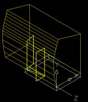
44. Join and close polyline and extrude.
Type: pedit (Press Enter)
Click on the newly created polyline.
Type: join (Press Enter)
Click once on the arc polyline.
(Press Enter)
Type: close (Press Enter)
Type: extrude (Press Enter)
Type: -30000 (Press Enter)
NOTE: Negative extrusion as it is going backwards in the z-axis.
45. Subtract fro the side window frame.
Type: subtract (Press Enter)
Click on the first of the window frame boxes created.
(Press Enter)
Click on the newly created polyline solid.
(Press Enter)
46. Create the next shape to subtract from the second window frame.
The arc that we copied needs to be moved so that it is away from the edge of the wall solid. I am moving it in as a precaution to guard against rendering problems in Radiance and Lightscape. When the edges of two solids overlap and are rendered sometimes the results can be very ugly.
Type: move (Press Enter)
Click on the arc.
(Press Enter)
Click on any point in the drawing window.
Type: @200,0,0 (Press Enter)
NOTE: This move can occur during the copying process. Instead of typing @0,0,0 in part 43 for the copy location we could have typed @250,0,0.
Type: pline (Press Enter)
Click on the bottom point of the moved arc.
With ORTHO on drag the cursor to the left of the screen to project a horizontal line.
Type: 10000 (Press Enter)
Move the pointer to the top of the drawing window to project a vertical line.
Type: 20000 (Press Enter)
Click on the top point of the arc.
Join and close the new polyline with the arc using the process described in part 44.
Extrude the polyline to create a solid.
Type: extrude (Press Enter)
Select the polyline
Type: -30000 (Press Enter)
Using the same process as described in part 45 subtract the new polyline shape from the second window frame.
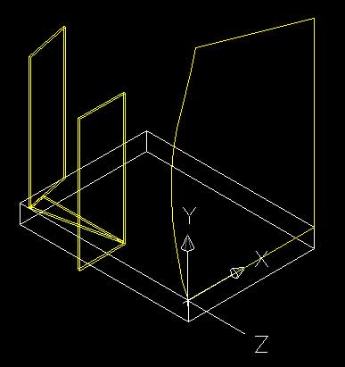
47. Create the top window frame.
Change to the world UCS.
Using the image below as a guide create a closed polyline ready for extrusion.
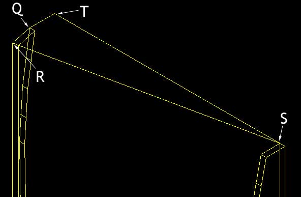
Type: pline (Press Enter)
Click on point Q.
Click on point R and S.
Type: @0,-8800 (Press Enter) (Point T)
Type: close (Press Enter)
Extrude shape.
Type: extrude (Press Enter)
Click on the new polyline shape.
(Press Enter)
Type: -200 (Press Enter)
Create a box for the second piece of the top window frame.
Type: box (Press Enter)
Click on the two points as shown in the image below.
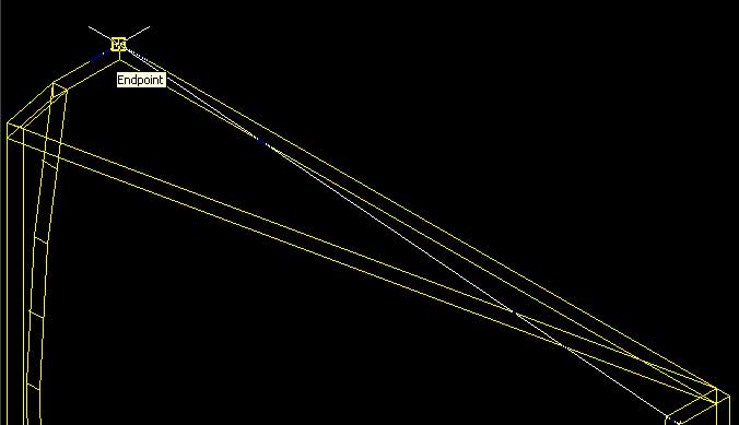
Type: 200 (Press Enter)
48. Join all the separate pieces of the window frame into one solid.
This is done to simplify the model. In Lightscape and Radiance light is calculated on how much hits an individual surface. By joining separate pieces together the number of polygons are reduced and the instances where polygons intersect are removed. This greatly increases the speed and quality of renderings. The shortfall of this process is that a union cannot be undone once a drawing has been saved and reloaded. You can undo a union but it must be through using the UNDO command (which only works for the current drawing session).
Type: Union (Press Enter)
Select all the solids that make up the window frame.
(Press Enter)
The separate shapes will be merged into one simplified solid.
Turn on the walls layer and check out your window frame.