49. Finally we will add the window glazing and accompaning framing. There are three methods for creating this glazing, a manual method for non-Architectural Desktop users and two automatic methods available within ADT.
Method 1: Manual Method
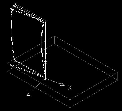
Select the SW Isometric viewpoint.Turn the walls layer off to simplify things.
Make the current layer 'construction'.
Restore the 'window plan' UCS.
Type: ucs (Press Enter)
Type: restore (Press Enter)
Type: window plan (Press Enter)
Or open the UCS dialog box:
->Tools ->Named UCS... and select the window plan UCS as current.
Set up a new UCS for the window elevation.
Type: ucs (Press Enter)
Type: y (Press Enter)
Type: -90 (Press Enter)
Type: ucs (Press Enter)
Type: z (Press Enter)
Type: -90 (Press Enter)
Save the UCS as 'window elevation'.
Type: ucs (Press Enter)
Type: s (Press Enter)
Type: window elevation (Press Enter)
The easiest process for creating the window is to create the frame-work and then fit the window to it.
50. Create the first horizontal frame element.
Type: box (Press Enter)
The beginning of the framework is 200 above the origin point (0,200,0).
Type: 0,200,0 (Press Enter)
Type: @-9300,100 (Press Enter)
Type: 150 (Press Enter)
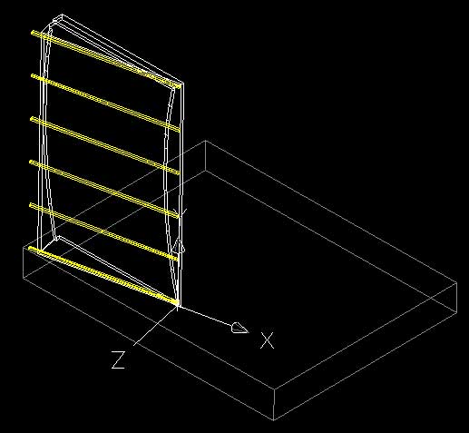
The most useful and now easy to use is the array function. This tool arrays a set of selected objects in a two-dimensional plane. It is very handy and effective when used to create windows or other repetitious elements in architecture.
Type: array (Press Enter)
The dialog box shown below should appear.

Set the below options in the dialog box.
Rows: 6
Columns: 1
Row offset: 2810
Click on the Select Objects button.
Select the horizontal element.
(Press Enter)
Click on the Preview button.
Your array should look like the image below. If it does click the Accept button to create the array.
51. Create a new box for the vertical elements and array.
Type: box (Press Enter)
Type: 0,200,0 (Press Enter)
Type: @-100,14150 (Press Enter)
Type: 150 (Press Enter)
Type: array (Press Enter)
Enter the following values into the dialog box.
Rows: 1
Columns: 9
Row Offset: 1
Column Offset: -1000
Click on the Select Objects button.
Select the vertical element.
(Press Enter)
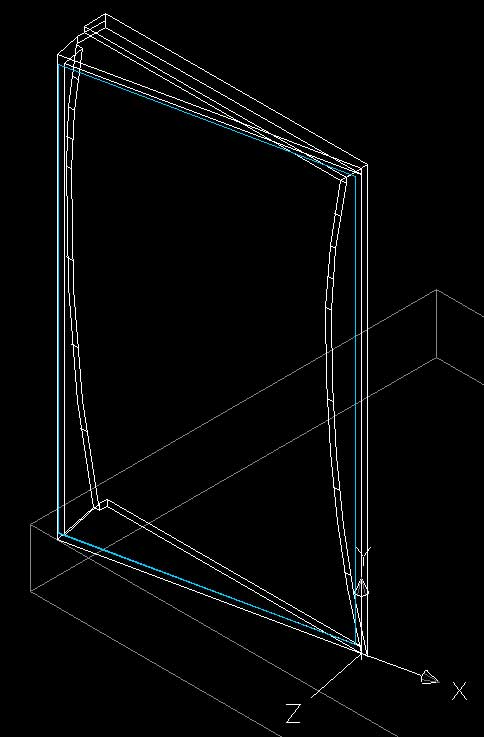
Click on the Preview button.
If the array looks like the image below choose to Accept the array.
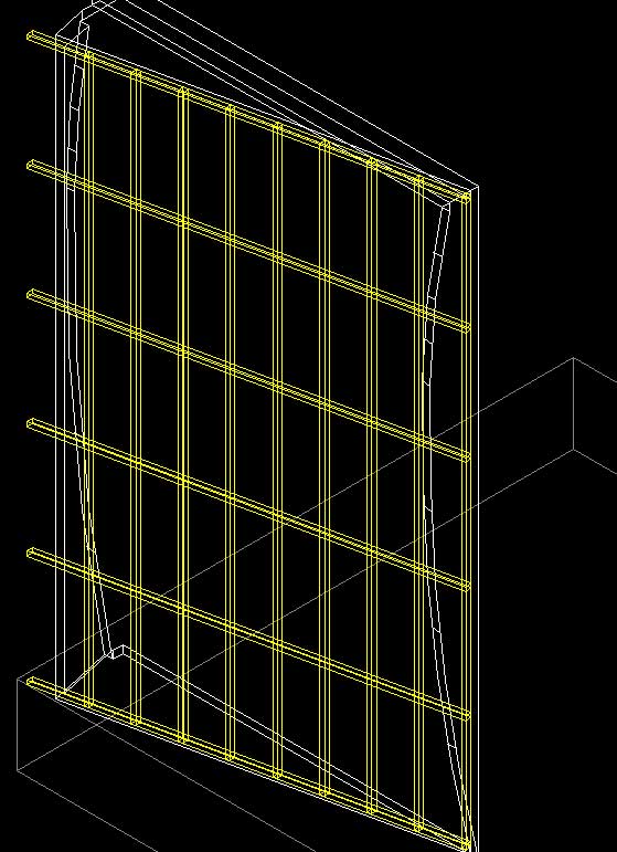
The final vertical element is at a different distance to the rest.
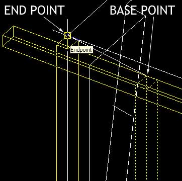
NOTE: In the actual building there is an angled frame element. For the case of this tutorial we will not model it. For a challenge (or if you were modelling this building for Assignment 1) you could try to create the angled frame element as visible in the image at the top of the page.
TIP: To create the angled shape you could use the rotate tool or angle the UCS to suit the desired angles.
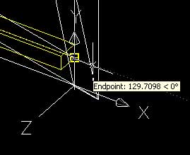
Type: copy (Press Enter)
Select the left most vertical frame element.
(Press Enter)
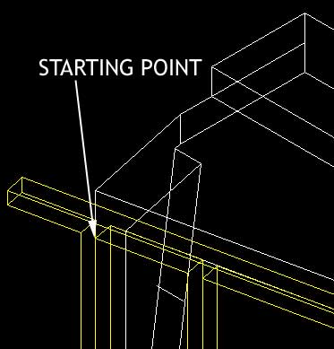
Click on the top corner of the selected vertical element.
Click on the top corner of the window frame as shown below.
This copies the element to the desired x position on the UCS but it is slightly too high.
Type: move (Press Enter)
Select the copied vertical element.
(Press Enter)
Click anywhere on the drawing window.
Type: @0,-100,0 (Press Enter)
To simplify the geometry we will union all the separate elements together.
Type: union (Press Enter)
Select all the horizontal and vertical window frame elements.
(Press Enter)
52. Finally we will create the window glazing and subtract a copy of the window framing grid from this single plane of glass to create individual window elements.
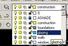
Create a new layer called 'glazing'.
Make it the current layer.
It is important that any glass or transparent objects have there own distinct layer. When it comes time for rendering in Lightscape or Radiance it is much simpiler to apply a glass material to an entire layer than parts of a layer. In Lightscape the glazing layer also needs to be defined as an opening for light or else you get a very dark interior.
Type: box (Press Enter)
Click on the point shown in the below image. It is at the top left of the window frame.
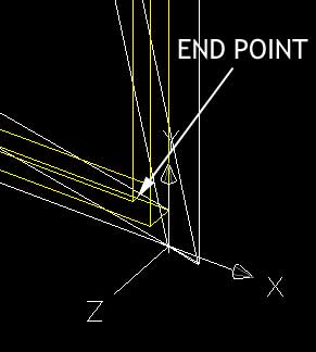
Click on the point shown in the below image. It is at the bottom right of the window frame.
Type: -5 (Press Enter)
Move the glazing backwards 15mm.
Turn the construction layer off.
Type: move (Press Enter)
Select the glazed element.
(Press Enter)
Select anywhere on the drawing window.
Type: @0,0,-15 (Press Enter) (Move backwards 15mm)
Turn the construction layer back on.
Make a copy of the window framing.
Type: copy (Press Enter)
Select the window framing
(Press Enter)
Select anywhere on the drawing window
Type: @0,0,0 (Press Enter) (Move to the same location as the original)
Subtract the copy of the frame from the glazing element to create individual pieces of glass.
Type: subtract (Press Enter)
Select the glazed surface.
(Press Enter)
Select the copy of the window framing.
(Press Enter)
Individual pieces will be created.
This process is done for the same reasons as described in section 46. By creating more geometry we actually reduce the work required of Radiance and Lightscape as they no longer need to calculate where the piece of glass and window frame intersect.
Change the remaining frame element from the construction layer to the window_frame layer.
Select the window frame element.
In the layers drop down list select the window frame layer.
The window element will be moved to the window_frame layer.
The main window is now complete.