Open up Revit and let us begin. This tutorial has been written using Revit 5.0. If you are using a newer version for this tutorial I can only hope the programmers have remained consistant in the tools and user interface available.
I have used a few terms related to the mouse that the uninitiated should be aware of.
Firstly whenever the term 'select' or 'click' is used it is implied the left mouse button will be used to perform this action.
Secondly the term 'click and hold' implies making a left-click but not releasing until the action is complete. Dragging actions are performed in this way.
Your first steps
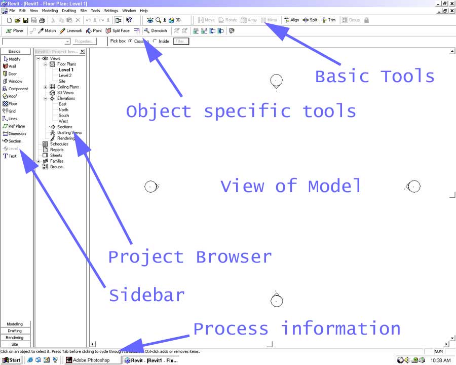
When Revit opens you should be presented with the blank default document as shown below (minus my notes).
Revit behaves like any Windows application. It is possible to arrange views on screen in any manner preferred.
If the view is maximized press the Restore Down button in the top-right corner of the window.
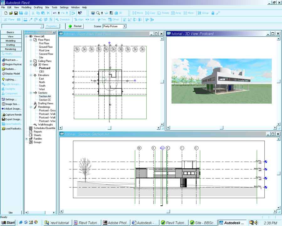
Using this feature your Revit workspace can be as complicated or as simple as you like. For the sake of this tutorial the active view will always be maximized on screen.
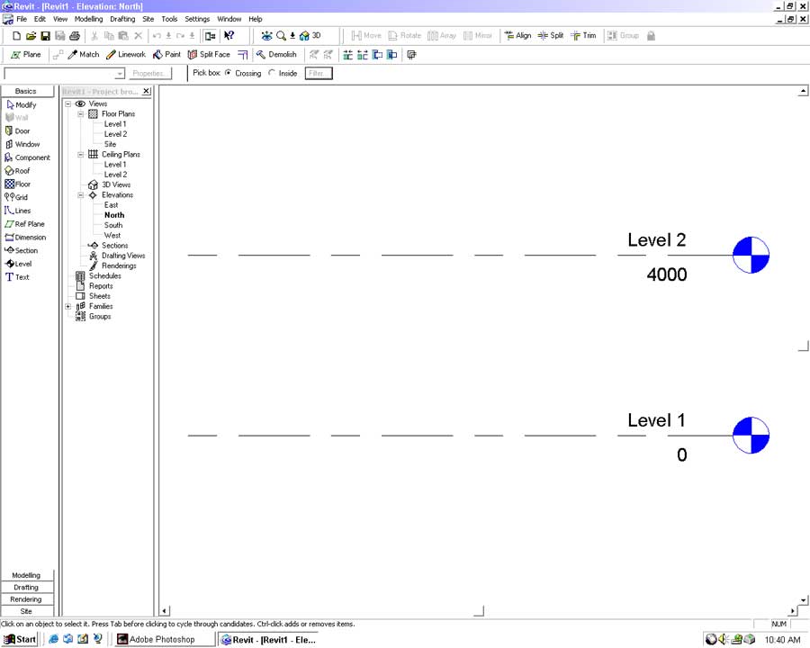
In the Project Browser open the North View by double-clicking North View in the Elevations menu.
The Modify tool is available in all the Sidebars and is used to select a single or group of objects.
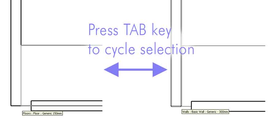
When two objects near or on top of each other they are often difficult to select.
We can cycle through objects beneath the pointer by using the TAB key.
With the Modify tool selected left-click on the Level 2 object. Press the right mouse button and select Properties.
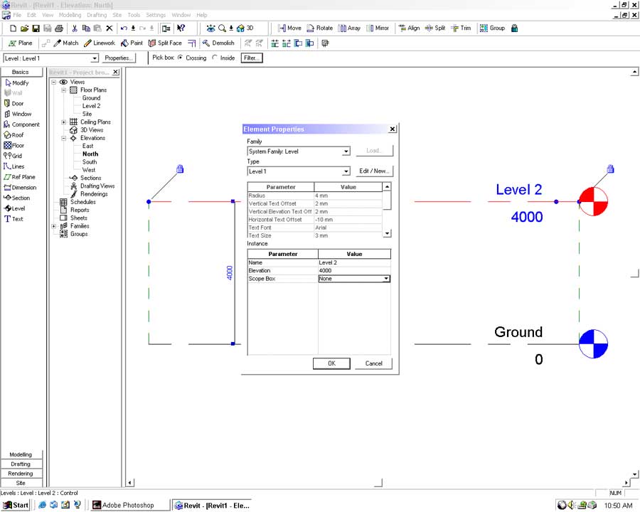
Set the following parameters:
Name: First Floor
Elevation: 3000
Press OK and agree to rename the corresponding views.
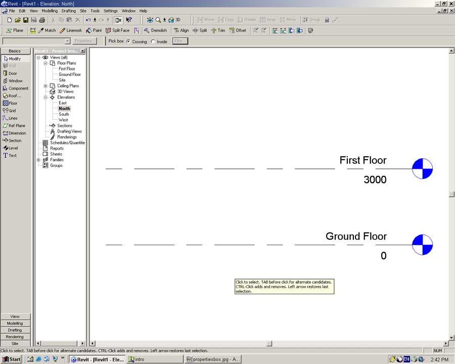
Left click twice on the Level 1 name tag. The pointer will change to a cursor. Rename Level 1 to Ground Floor and press (Enter). Agree to rename the corresponding views.
We will now place a second floor level. Levels are very important in Revit because they establish vertical relationships within and between objects. Be careful not to place too many Levels as relationships within and between objects can get difficult to manage.
From the Basics (or Drafting) Sidebar select the Level tool.
Move the pointer into the modeling window. You will notice the pointer is a pencil with a height line relative to the closest Level plane.
Move the pointer above the First Floor on the left hand side. Left click once to begin placing the Level object. Move the pointer to the far right and left click again as shown below.
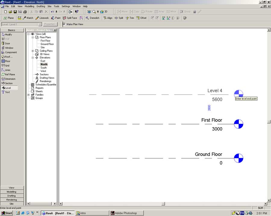
Accuracy is not a problem when placing objects so don't worry exactly where your level is at the moment, we will fix that later.
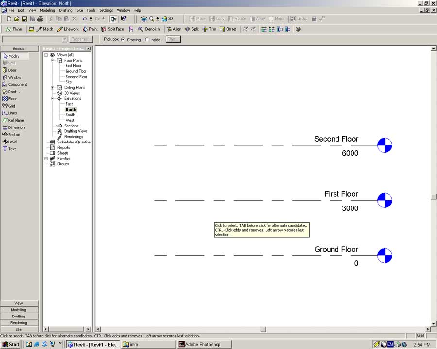
With the Modify tool select this new level. Bring up the object's properties by either:
Right clicking and selecting Properties
Double clicking directly on the name/height text boxes
From the Menu select -> Edit -> Properties
Set the following properties for the object:
Name: Second Floor
Height: 6000
With the height lines in place we will create boundary lines for the site. In reality most buildings will have reasonably complex boundary lines and very accurate definitions of where they are. For this tutorial we are just going to have a square block of land.
Double click the Site view in the Project Browser to open it.
Open the Site Sidebar and select the Property Line tool.
Choose to create the Property Lines by sketching.
The Sidebar will change to the following subset of Property Line commands.
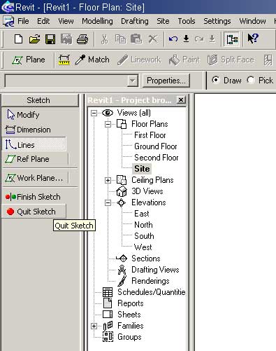
Select the Lines tool. A collection of Lines tool options will appear below the main toolbar.
![]()
Using these commands it is possible to form complex two-dimensional shapes. The Chain tick-box instructs the Lines tool to create a series of linked lines as you sketch. Without this enabled only one line at a time will be created.
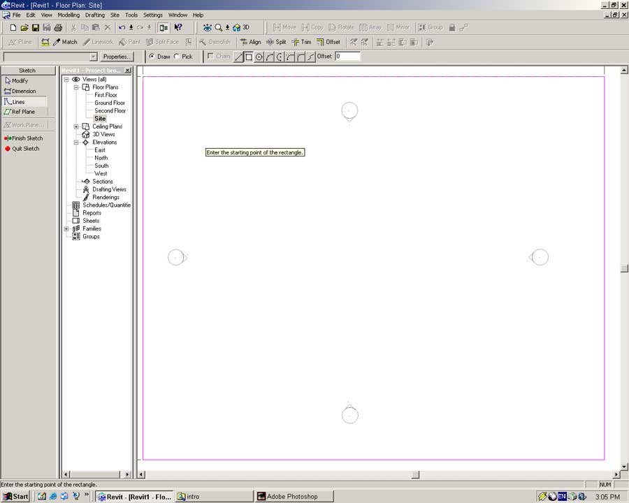
Select the Rectangle option of the Lines tool.
Click at the bottom right corner of the screen. Move the pointer to the top left of the screen and click again to complete the box. Do not worry about accuracy, we will set the correct dimensions for this Property soon.
Zoom out a little to get a clearer picture. To zoom out either:
Use the scroll-wheel on the mouse.
From the menu select -> View -> Zoom Out
Right Click on the Model Window and select -> Zoom Out (2x)
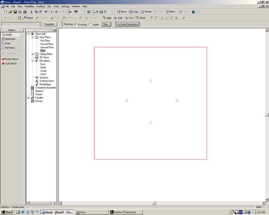
Select the Modify tool and click on the rectangle.
Click on the left hand line. Click on the dimension value and type 60000 (Enter).
Click on the top line. In the dimension field type 60000 (Enter).
You should now have a box with dimensions of 60000mm by 60000mm.
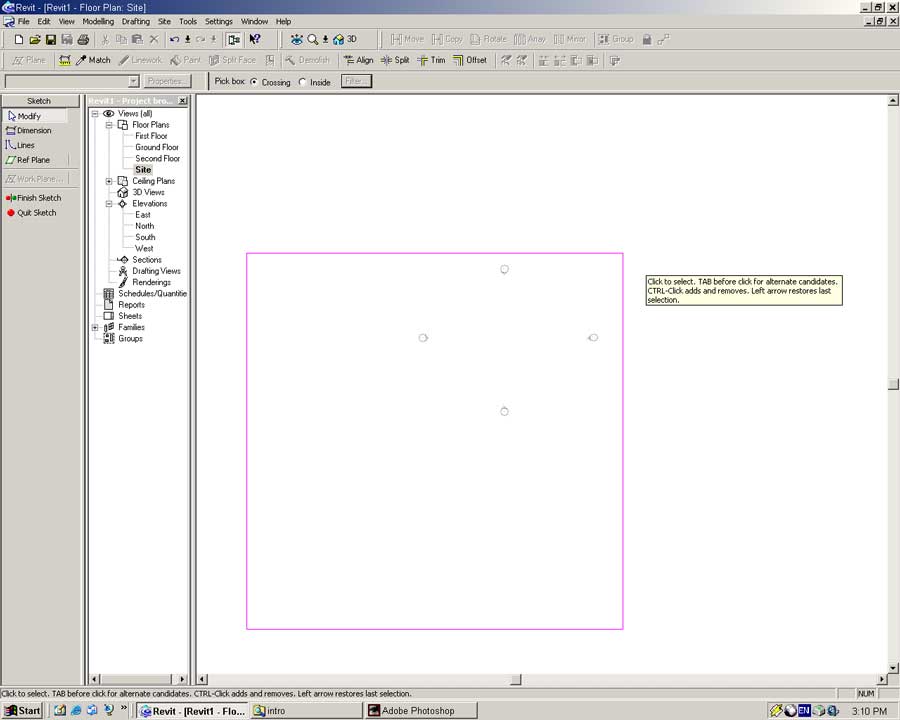
With the Modify tool select the four lines that make up the Property box, either:
Click and drag a box around the four lines.
Whilst holding the CTRL key click on each of the four lines.
Move the pointer over one of the selected (red) lines. The pointer should change to a move cursor. Click and drag the property box so the four view indicators lie at its center as shown below.
Select Finish Sketch to create the Property.
From the File menu select Save. Select a location for your work and enter a relevant name for this file. Press Save to save the file to disk.
As a suggestion I would recommend saving each Revit document into its own directory.
This has two benefits. Firstly Revit saves multiple versions of your document to disk during routine operation to ensure data security. If your main file becomes corrupt you always have other automatically created backups. Whilst handy it can be confusing especially when mixed with other documents.
Secondly Revit projects usually consist of a series of interlinked files related to a single project. By saving all your files into a project directory you minimize the risk of accidentally loosing a vital file. As a CAD tutor for many years I know this happens to people (even smart ones) very regularly!