This page looks at just a few of the new features in Revit 9.1
Room Objects and Colour Schemes
These tools are particulary helpful in identifying rooms, and can be used to calculate floor areas, create schedules with surfaces and much more. This tutorial will just touch on the basics.
We will use the ground floor to create a room colour scheme
Open the ground floor view
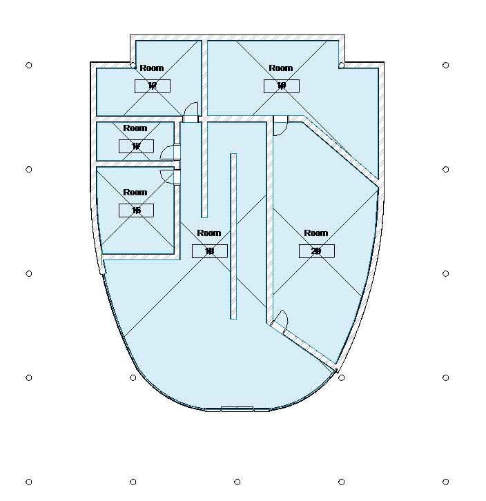
Before we start we need some more walls, so download the link below which is an image showing the placement for the walls on the ground floor. Save it in an appropriate directory and then in Revit import it just as you did on page 10 (with the second floor plan)
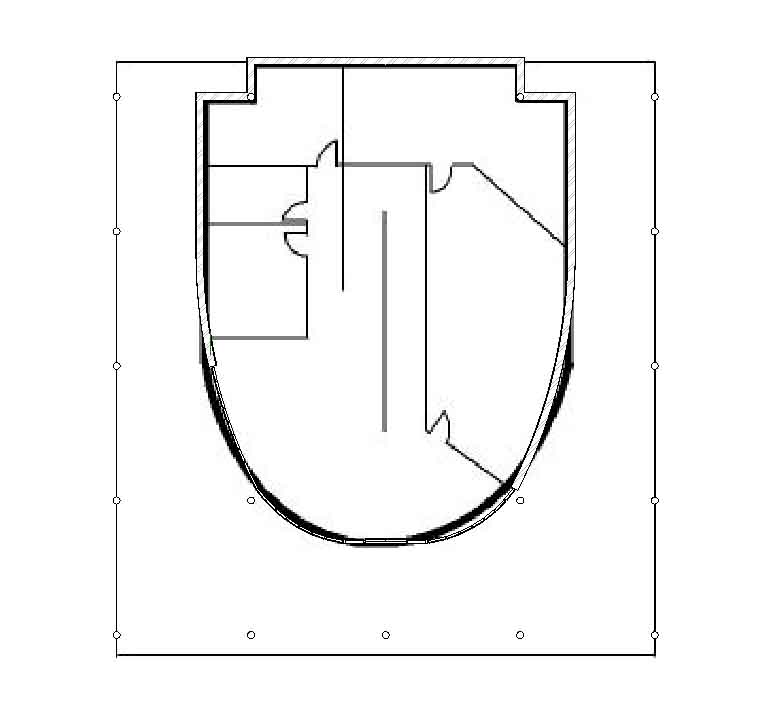
Line the image up with your building model
Turn of the grids, section lines and elevations. Right click on the model > View Properties > Edit Visability > Annotation Categories. Uncheck Grids, Sections and Elevations then press OK
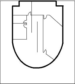
You should now have something looking like the following:
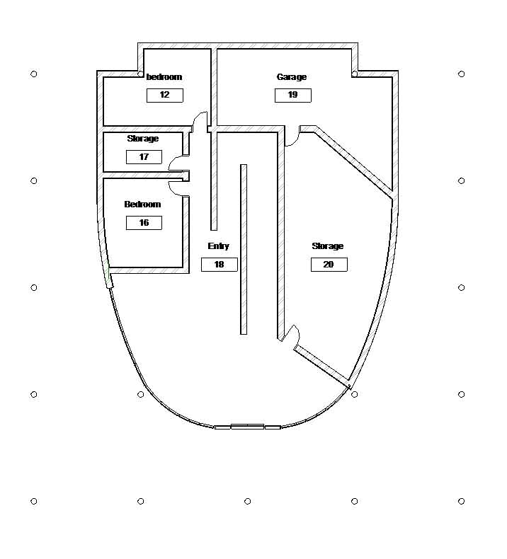
Trace over the internal walls with the Villa Savoye Ground Floor wall and place some doors in the correct position (it doesn't matter what type of door you use)
When you have finished you can turn off the Raster Image (for the ground floor), by opening the View properties. Press Edit in the Visibility field.
Uncheck the Raster Image option in the dialog and press OK.
(Typing VV is a shortcut to bring up the visability dialogue box)
With these in place we can now set up a Colour Scheme.
Right-click the ground floor view in the project browser view.
Click Duplicate View > Duplicate
Right-click the copy of ground floor
view. Click Rename.
Change the Name to Ground Floor -Room Areas
Click OK.
In the Ground Floor - Room Areas view,
type VV to access the view’s graphic overrides.
Under the Site Category, clear Property Lines.
Click OK to close each dialog box.
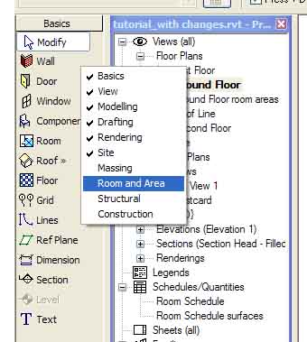
If the Room and Area design bar is not available, right-click the design bar. Click Room and Area to open the tools. (as shown in the image below)
On the Room and Area design bar, click Room, and set the options bar to the following settings
Upper limit First Floor
Offset 0
With the room tool selected, click in the centre of each room including the entry hall. you should end up with something similar to this
Click Modify and rename each room by double clicking on the text in each room
Name the rooms as I have below
On the drafting design bar, click Colour Fill
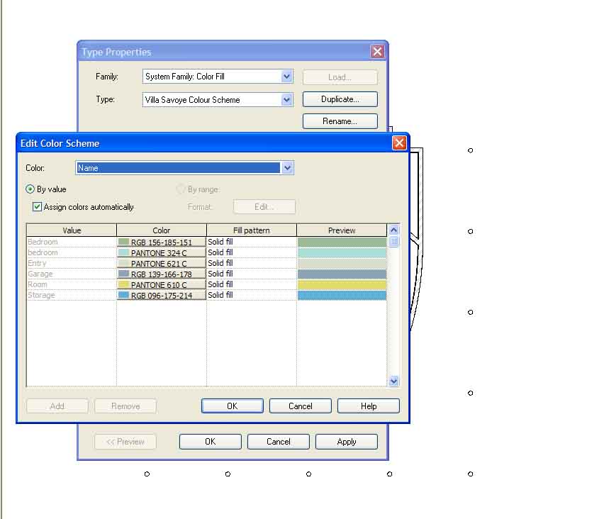
Open up the Properties and under type click Edit/New > Duplicate
and call the new colour scheme Villa Savoye Colour Scheme, then click OK
Under Colour Scheme click Edit
Under colour, change the title to name. You should have something similar to this, feel free to change the colours.
Click OK to close the dialogue boxes, then click to the side of the drawing to place the colour key. Automatically the colours should be layed over each room to match the key, just like below.
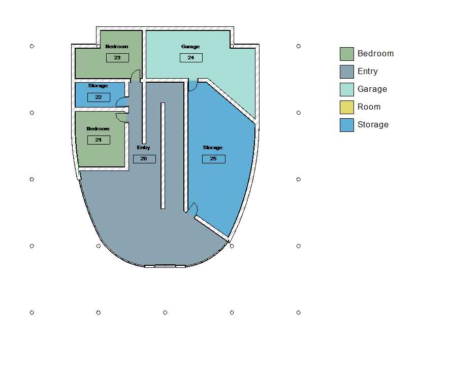
With these rooms in place we could then go on to make up various schedules for wall and floor finishes and you can also calculate percentages of each room type but we leave that for you to experiment with later.
Perspective Sections
Perspective Sections are particulary useful for presentations as they show a lot more than normal perspectives and section drawings, and they're reasonably easy to generate from Revit
On the ground floor, place a camera on the south of the building (looking north)
In the camera view, right click ond click on View Properties.
Under the Extents heading check the Section Box.
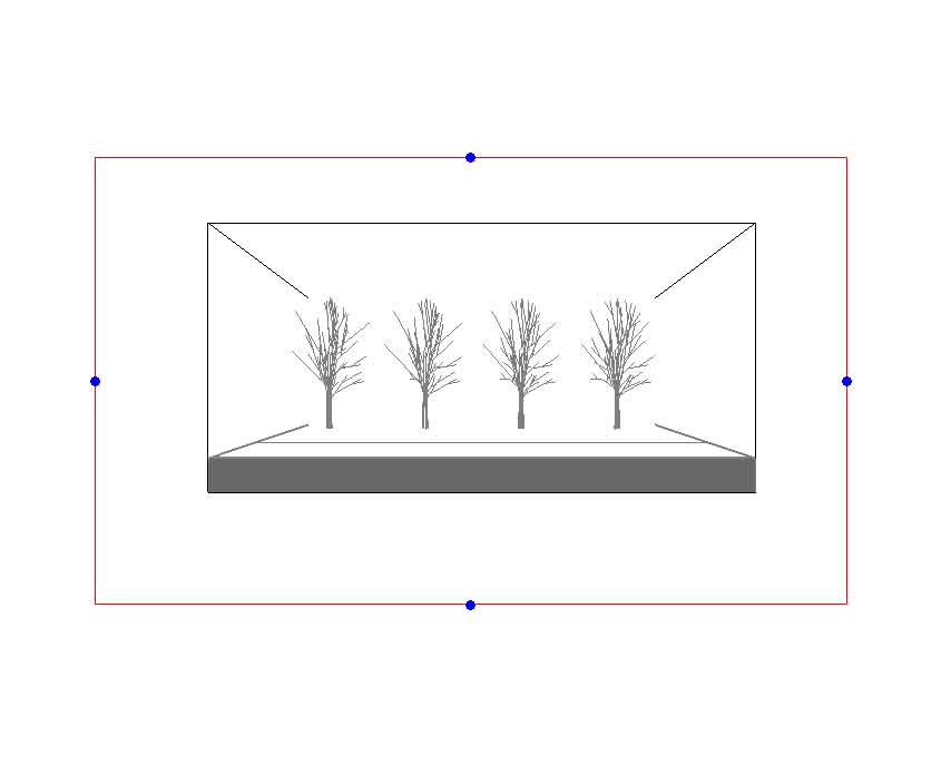
The next bit can be tricky but stick with me and hopefully it will work. The image below shows what I got when I turned on the section box, (the clipping plane is beyond the north end of the building so the building is not visable) don't worry if yours looks different. Hopefully you will have two boxes around the outside of the image, the outer one (the red one) is the boundary of the camera view and the inside one is the boundary for the section box. Make sure you have a decent gap between the two boxes.
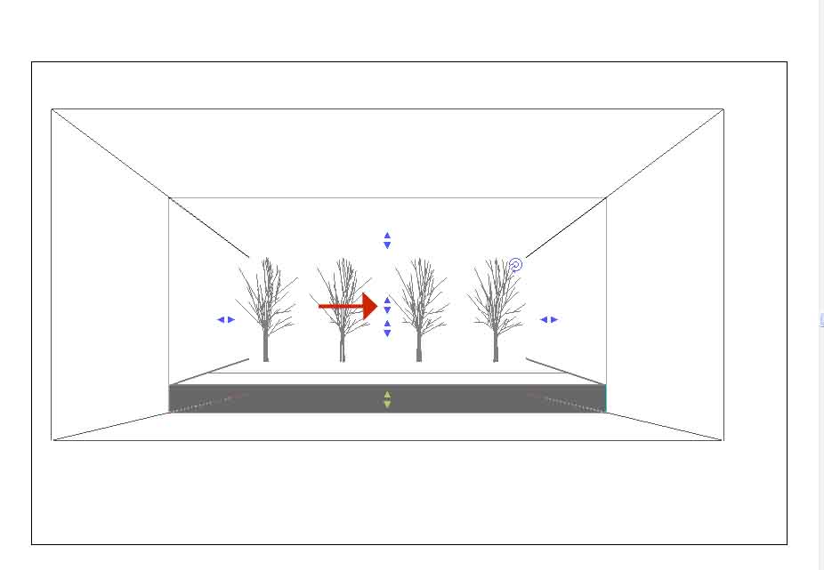
The next step involves dragging the section box out so you can see more of the building/find an appropriate place to section the building through. To do this you need to select the boundary for the section box (the inner box). When selected you will see six sets of blue arrows appear. You need to find the set of arrows that will drag the boundary closer to you (to allow more of the building to appear. I have shown with a red arrow the correct set of arrows on my perspective. Yours should be somewhere near the centre of the page. You can experiment by clicking on the various sets of arrows and dragging them in either direction, as you drag the arrows you will notice more/less of the building appears.
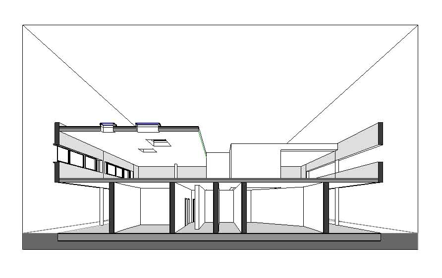
Keep playing with the blue arrows until you find a view which you are happy with. Below is what I ended up with
Importing a SketchUp File into Revit
Google SketchUp is a light-weight computer modelling program which enables 3D models to be created in very little time. It is very useful for quickly modelling simple elements or preparing a conceptual 'sketch' of how things are intended to look. Even better there is a free version that anyone can download and try out with no obligations to buy.
Note: If you are a new Sketchup user I recommend watching some (or all) of the SketchUp Show. This is a regular video podcast illustrating how to use many of SketchUp's features in an easy to follow a long with manner.
Often a combination of more than one CAD program is used to generate computer models. This section goes through how to import SketchUp files into Revit.
For this exercise we will import a SketchUp model of the surrounding buildings/trees around the Villa Savoye
To begin, download the link below which is the SketchUp model. To download it click on the link, when the file save dialogue box appears, click Save, and choose an appropriate directory to save it in
Back in Revit make sure the 3d view is the current view.
To import the file
File > Import/Link > Cad Formats
Change the file type to SketchUp Files (*.skp)
Locate the file
Change the Layer/Level Colours to Preserve Colours and change the positioning to Origin to Origin.
Then click Open to open the file, you should hopefully have something similar to this
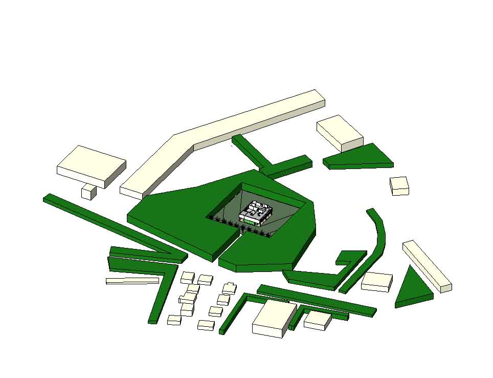
The surrounding trees are represented in the model through the green blocks. I did not use the tree component tool in SketchUp as the components increase the file size significantly and for the purpose of this exercise, blocks will provide similar sun study results to that of the trees.
As I gave you the SketchUp file to import for this tutorial, you didn't have to go through SketchUp. However next time when you're using your own SketchUp file just save the file as a normal SketchUp file (I used SketchUp version 5 as the file type) and then follow the same steps as in this tutorial.
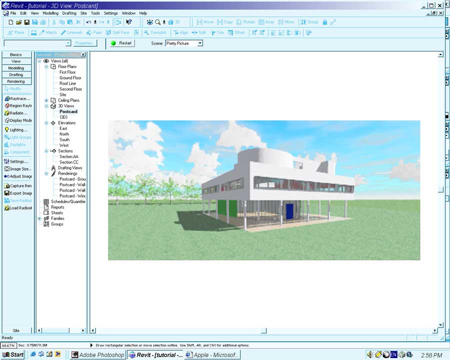
Stand up and give yourself a clap. That is the end of the modeling aspect of this tutorial. There is plenty more we can do but for now it is time to take a break and render a nice Postcard image of your hard work.
The next stage of this tutorial will quickly look at laying out sheets for printing and exporting Revit models.