Last but not least come the windows of the Villa Savoye.
Before we place actual windows we will create a void in the eastern wall using an Opening object. The Opening object is like a window but it has no geometry.
From the menu select -> File -> Load from Library -> Load Family...
Browse to the Metric Library/Windows folder and open the M_Opening.rfa file.
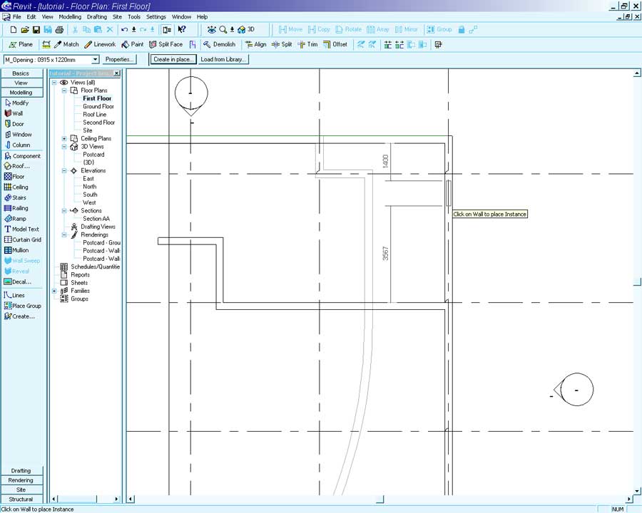
Open the First Floor view and zoom in on the north-east corner.
From the Modeling Sidebar select the Component tool.
Set the Component Type to M_Opening: 915 x 1220mm and place a single instance in the eastern wall (anywhere you like).
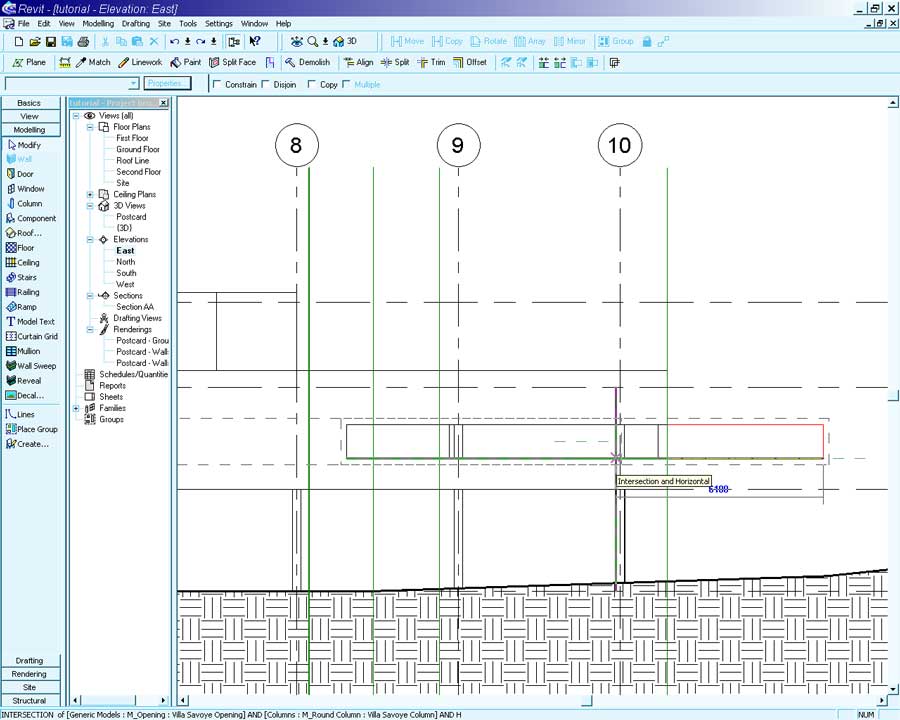
Open the east elevation and zoom in on the opening.
The opening we are creating will extend from Gridline 10 to Gridline 7.
Use the Tape Measure tool to find the distance between these two points (14000mm).
Now that the width of the opening is known we can create a custom object.
Select the Opening with the Modify tool and bring up its Properties.
Press the Edit/New button and select Duplicate.
Name: Villa Savoye Opening (Enter)
Width: 14000
Sill Height: 1200
Height: 1000
Press OK. An error message will probably appear informing you that the relationships between the different wall elements will be effected by this object. Choose to ignore it.
You should now have a large opening that may extend past the end of the building.
We will now move it to the correct position.
With the Modify tool select the opening.
Select the Move tool and click once on the bottom left corner of the opening.
Move the mouse to the left-hand edge of the first column as in the screenshot below.
The opening should move to be in the same position as illustrated.
Open the First Floor View and place a Section Line (from the Basics Sidebar) running east/west along the center of the model.
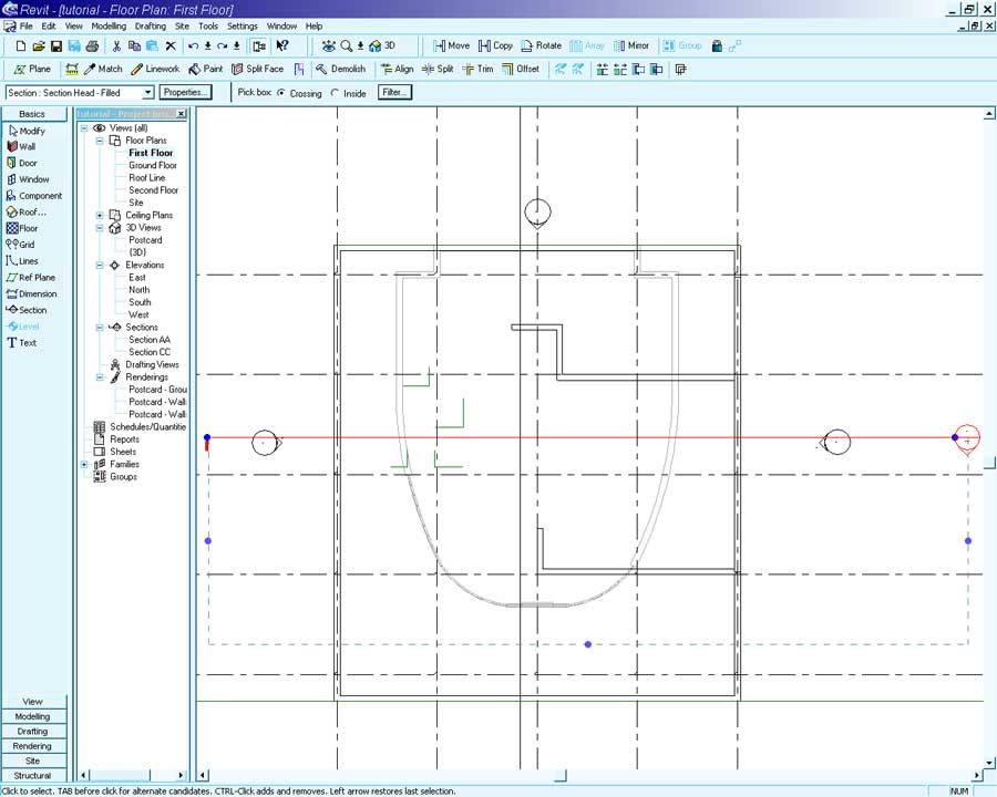
The Section needs to be looking north.
If your section is facing the wrong way right-click on the section line and select Flip Section.
Open the new section in the Project Browser.
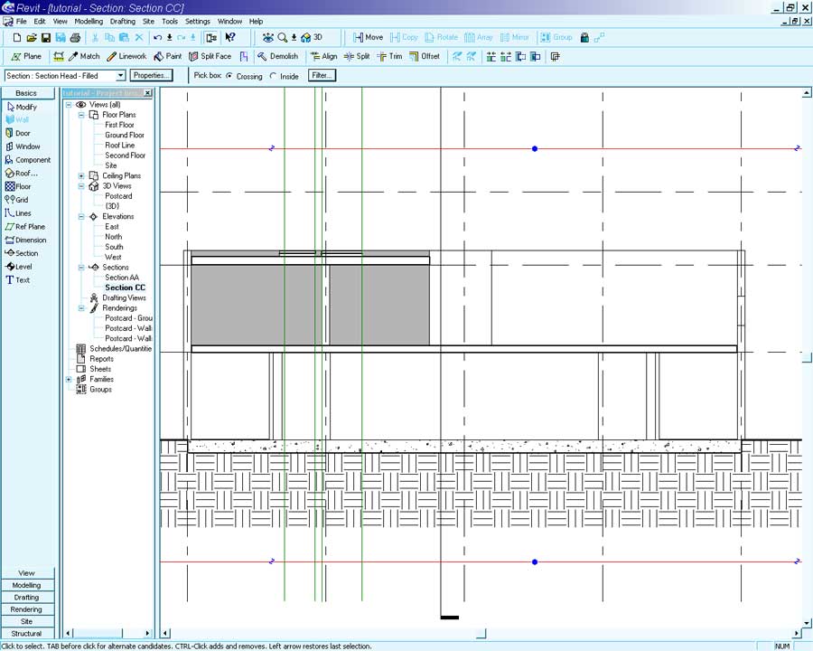
Select the highlighted wall and press the Edit Elevation Profile button.
We want to edit the profile of this wall so that this it is flush with the internal column.
From the intersection of the Second Floor and wall profile click once:
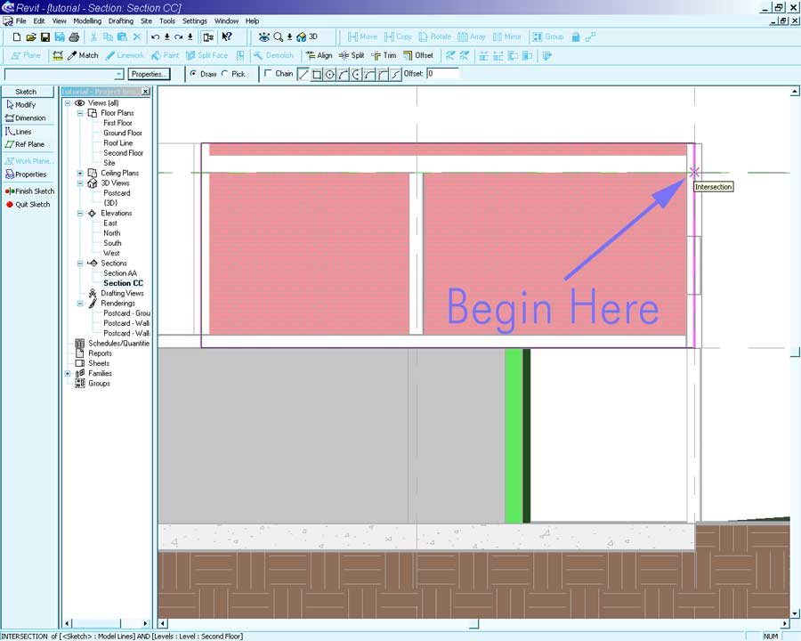
Place the end of the line flush with the column.
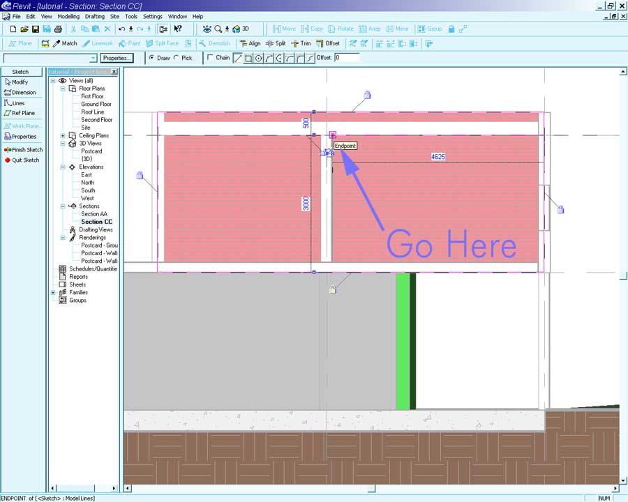
Place another line to the floor level. Move the existing two wall profiles back to meet the new line segments. The following shape should be formed.
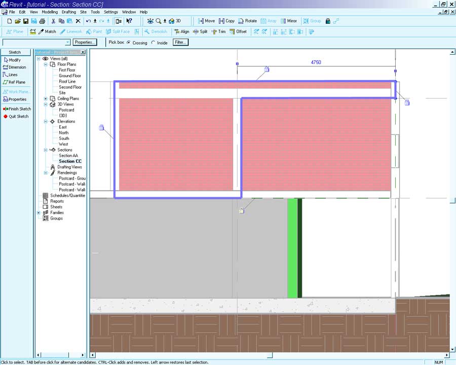
Press Finish Sketch in the Sidebar to reconstruct the wall.
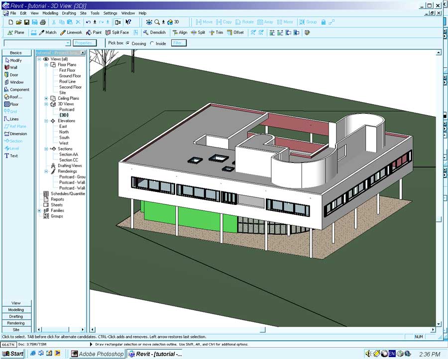
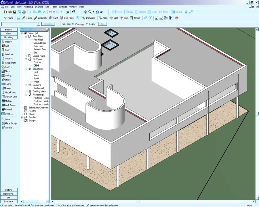
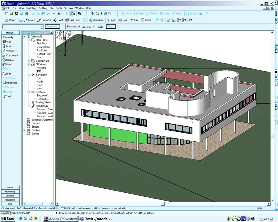
Switch to {3D} and checkout the new opening.
Enclose the space by placing a new wall with the following settings:
Type: Villa Savoye First Floor
Location Line: Core Centerline
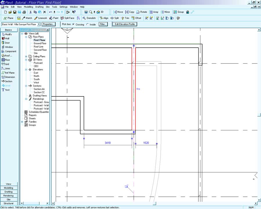
Open the First Floor view.
Begin the wall at the edge of the new opening and end at the intersection with the northern wall.
Extra for Experts: Starting A New Family
This section is for those wishing to extend themselves.
If you are not that way inclined you can download the Window family created in the following section of the tutorial and move on to the next section ' The Home Stretch'.
Right click on the link below and select 'Save File As' to save the Window family to your working directory.
But for those who want a challenge.....
Rather than using a boring library component for the windows of the Villa Savoye we will define a new window family especially for the project. This has two benefits.
Firstly reliance on Revits standard libraries can lead your model to look generic and dull. Secondly external custom families allow a project to be broken down into a series of small tasks handled by different people at different times. Modifications made to the custom family flow through into the project model, making it easy to modify an aspect of a model automatically.
To create a new family from the menu select -> File -> New -> Family...
Browse to Templates and open the Metric_Window.rfa file.
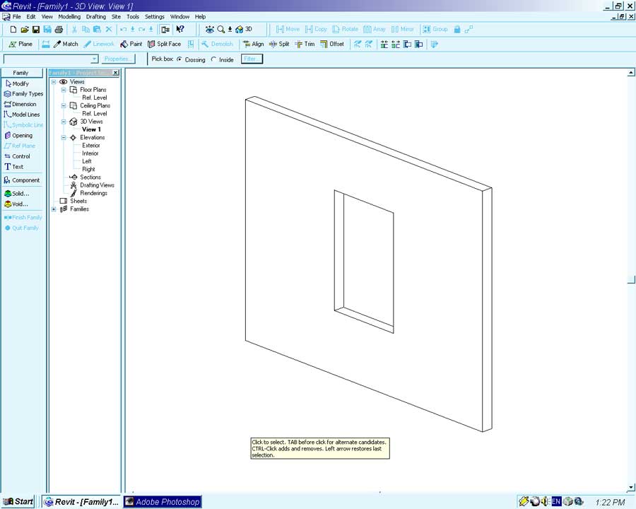
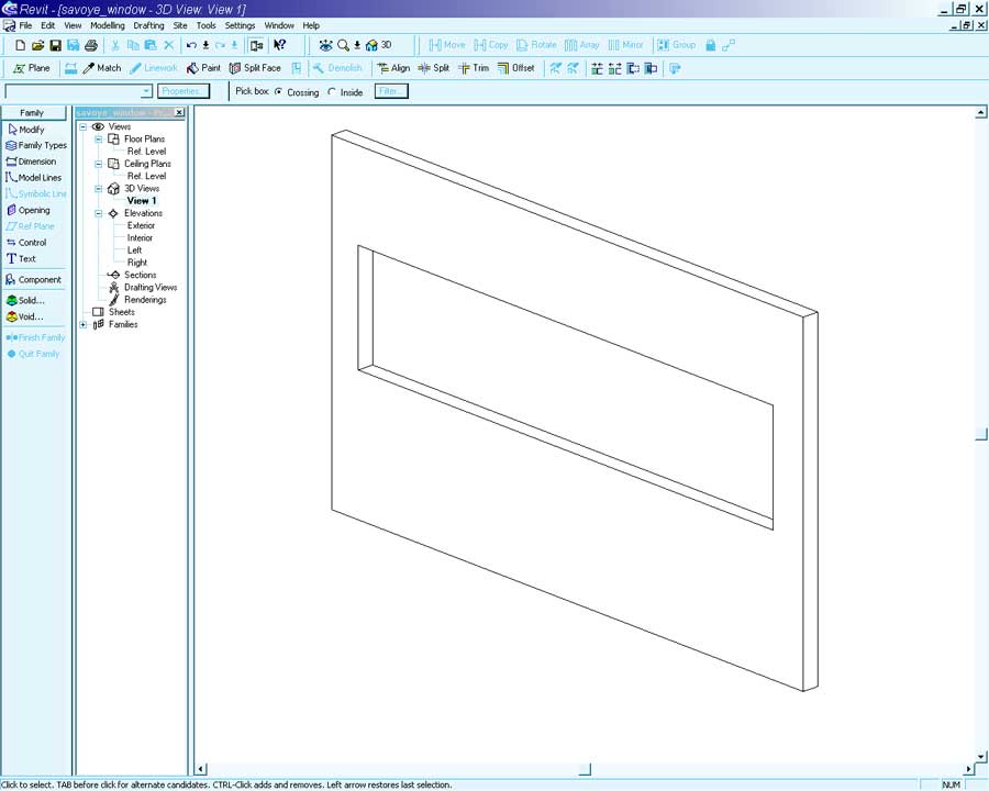
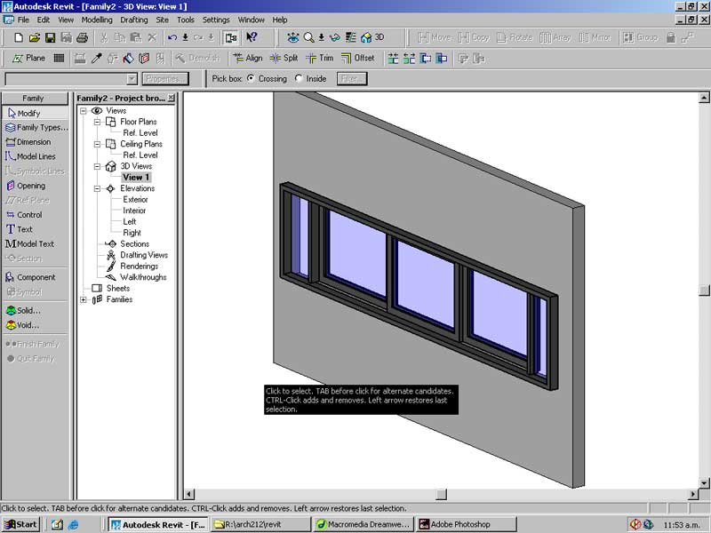
After the file has opened you will notice the reduced Sidebar tools and views available in the Project Browser.
When creating a family the different views take on important meaning. The 3D Views -> View 1 is how the object will appear in 3-dimensional views. The other views illustrate what the object will look like in plan, section and elevation.
It is possible to have different geometry and details appear in plan, section and 3-dimensional views (similar to the tree object). The specifics on how to achieve this will not be dealt with in this tutorial.
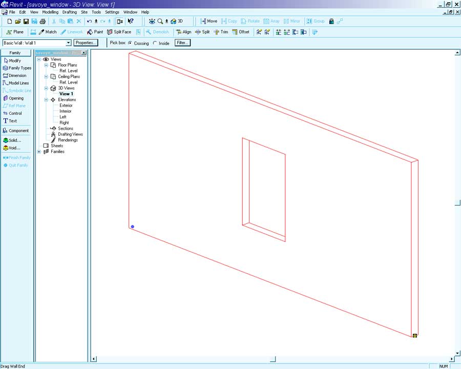
As the window we will be creating is 4500mm long select the wall ends and drag them outwards to stretch the size of the wall.
Press the Family Types button in the Sidebar and select New Type from the dialog.
Name: Villa Savoye Window (Enter)
Height: 1000
Sill Height: 1000
Width: 4500
Using Reference Planes we will define the position of the window mullions. Revit has a very flexible system for creating objects. In a custom family dimensions can be set by parameters or complex formulas.
When defining a new family the use of Reference Lines are very important. Reference Lines are the objects all other things are placed relative to. When a reference line is moved objects placed in relation to that reference line are moved as well (unless they are locked in position).
The objective of this window family is to be able to specify a width for the window and have the geometry adjust itself to the new parameter. This will allow us to make windows of various sizes from the same Window family.
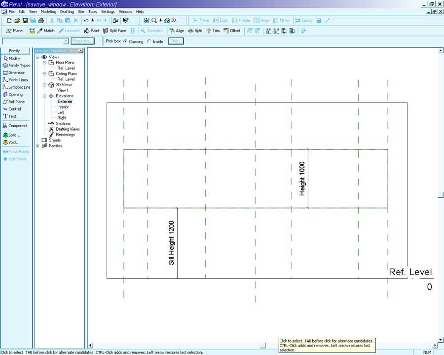
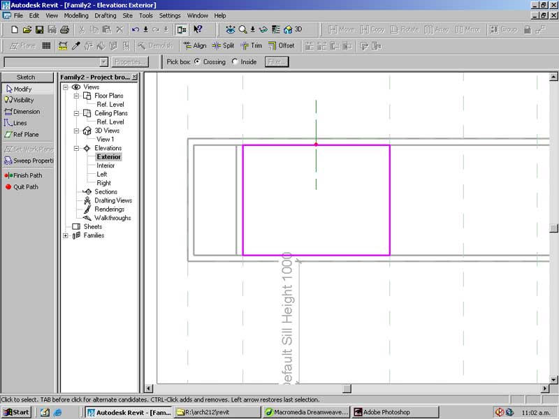
Open the exterior elevation.
Place four Reference Planes as shown below.
Do not worry about their exact location, as you probably know by now we will set that later.
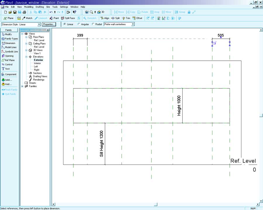
Select the Dimension tool. Dimension the spaces between the two outside lines.
To create a dimension click on the first line, move the pointer to the next line and click again. Finally move to the position where the dimension line will be and place it with a third and final mouse-click.
When creating a new family it is possible to specify a name for a dimension. When a name is given to a dimension it becomes a parameter of the object. This allows us to easily change an aspect of the object without having to modify the underlying geometry. At first this idea may sound confusing but believe me with a little practice and understanding it will save you a lot of time and stress.
To name a dimension select the Modify tool from the Sidebar and click on the dimension.
In the Label dropdown select .
In the Parameter Properties enter the following:
Ensure Family parameter is checked
Name: Gap
Value Stored By: Type
Press OK.
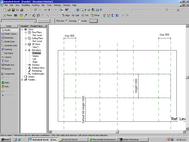
One of the dimensions should now read Gap:
Set the distance between reference planes on the other side of the window to read the same as the dimensioned distance.
Select the other dimension line and from the Label dropdown select Gap.
Rather than having a static Gap we will make the Gap proportionate to the width of the window.
Open Family Types... from the Sidebar
In the Formula field for the parameter Gap enter the following: Width/10
Press OK.
This formula will make the Gap value equal to 1/10 of the Width parameter.
(Applause from the audience) BUT WAIT, THERES MORE!
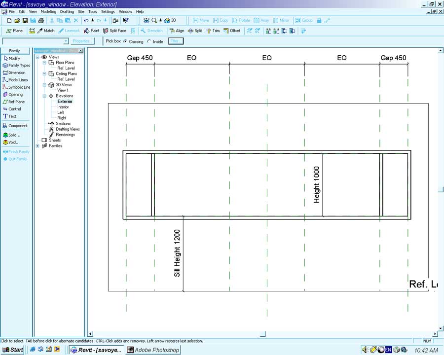
We will create a continuous Dimension Line between the four vertical Reference Lines.
Activate the Dimension tool from the Sidebar and click on the left hand Reference Plane.
Move from left to right clicking on each Reference Plane as you go.
When you reach the end move the pointer up and place the Dimension line with a final mouse-click.
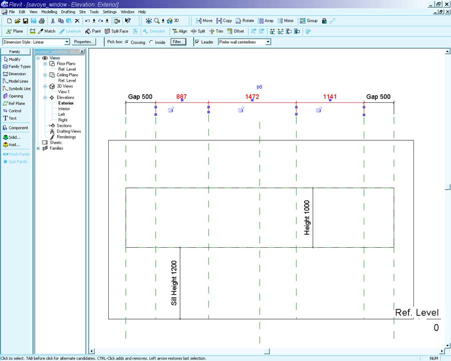
The mullions on these Reference Planes will be spaced equally apart. Revit can automatically achieve this for us.
Click on the EQ symbol above the Dimension line to evenly space out the Reference Planes.
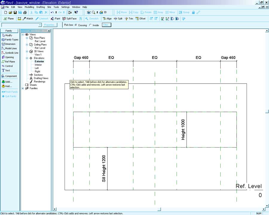
Wow! Just like that we have created a very flexible framework for building our window.
With a framework in place we can begin creating the geometry of the window.
When creating 3-dimensional geometry for new Families basic solid objects are used. These solid objects can be added or subtracted from each other to create very complex shapes. Those of you familiar with AutoCAD will understand the process of solids modeling.
Click on the Solids tool in the Sidebar.
A dialog will appear illustrating the four different methods of solids modeling in Revit. The four different methods are illustrated quite nicely by the images and text (which is very nice of the software developers).
Select the Extrude option in the dialog.
The Sidebar will change to reflect the tools available when creating solids geometry.
This tool is very similar in principle to the Roof or Floor tools.
Use the Lines tool to construct a profile to extrude.
Create a 50mm thick framing profile in the Exterior Face view as shown below.
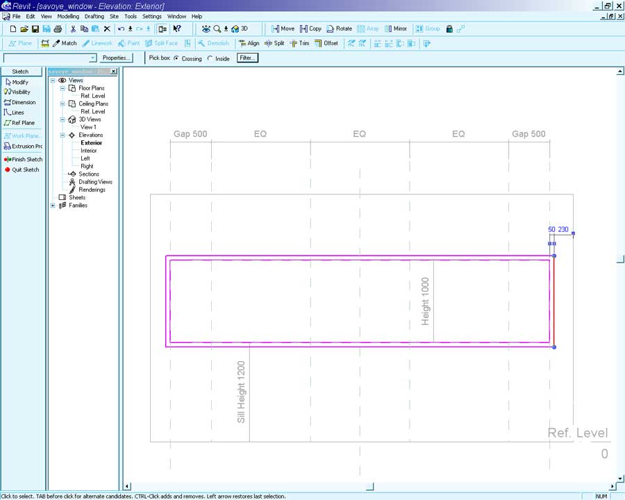
Open the Extrusion Properties by clicking on the button in the Sidebar. Set the following properties:
Extrusion End: 0
Extrusion Start: -100
Material: Black Steel (you will need to define this material beforehand)
These settings begin the extrusion of the profile -100mm above the External Wall Reference Plane and end it at the Planes base.
Close the Properties dialog and press Finish in the Sidebar.
We will create some small mullions using the Solids Extrusion method again.
Activate the Solids tool in the Sidebar, select Extrude in the dialog and press OK.
Select the Lines tool and enable Chain in the toolbar.
Create the shape shown below (it is 50mm wide).
Open the Extrusion Properties and set the following properties.
Extrusion End: 50
Extrusion Start: -50
Material: Black Steel
Close the properties and Finish the solid.
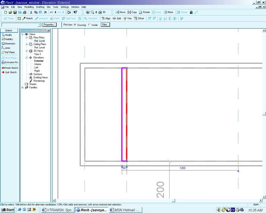
Using the Copy tool create a copy of the mullion at the other end of the window.
Select the newly created mullion with the Modify tool.
Activate the Copy tool. Click on the top-left corner of the mullion as the first point.
Set the second point as the intersection between the third Reference Plane and the top window frame.
The copy should be made in the position illustrated below.
Now place some glass in the two spaces formed by the mullions.
To do so we will yet again use the Solid Extrusion tool, it is very handy!
In the Sidebar select Solids tool and in the dialog chose Extrusion.
Activate the Lines tool and select the Rectangle option.
Draw rectangles in the two small spaces formed by the mullions.
Open the Extrusion Properties dialog and set the following parameters.
Extrusion End: 0
Extrusion Start: -5
Material: Glass
Finish the extrusion.
With our little side windows made we will now create our larger main window openings.
To create the larger window we will define a profile that is extruded along a path to create a solid.
In the Sidebar select -> Solid... -> Sweep
This window will be created on the Interior Working plane.
Think of Working Planes as flat pieces of paper on which you draw your 2-dimensional sketches. By using the Interior reference plane the frame will be sunk back in the window opening.
From the menu select -> Tools -> Set Work Plane
In the Work Plane dialog select Interior from the dropdown and press OK.
In the Sidebar select the Sketch 2D path tool.
Sketch a 2d path as shown below.
Press the Finish Path button on the Sidebar.
From the Sidebar select the Sketch Profile.
In the Go to View dialog select Elevation Left and press Open View.
In the opened view zoom in on the red dot and sketch the following profile.
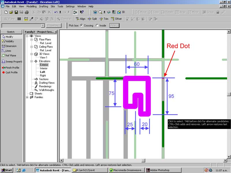
Press the Finish Profile button in the Sidebar.
Select the Sweep Properties tool and set the Material to Black Steel.
Press OK and then select Finish Sweep.
A sweep will be constructed that will form the frame for the window. Now lets create the glass for it.
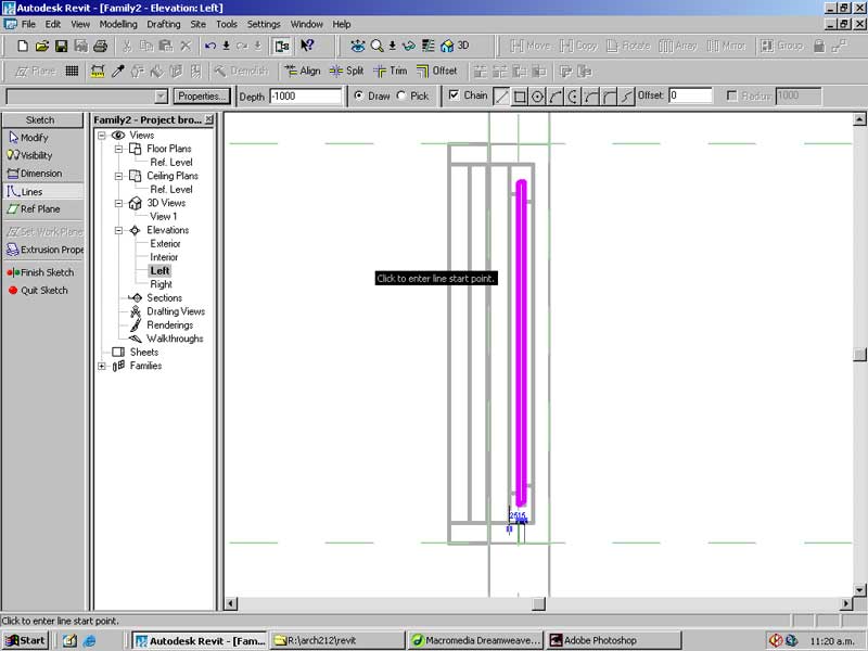
Open the Left Elevation.
Create an Extrusion with the following profile.
Set the following Properties for the extrusion:
Extrusion Start: 0
Extrusion End: 1000
Material: Glass
Press OK and select Finish Sketch.
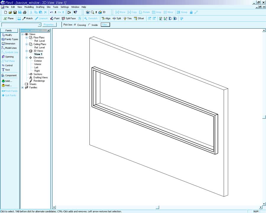
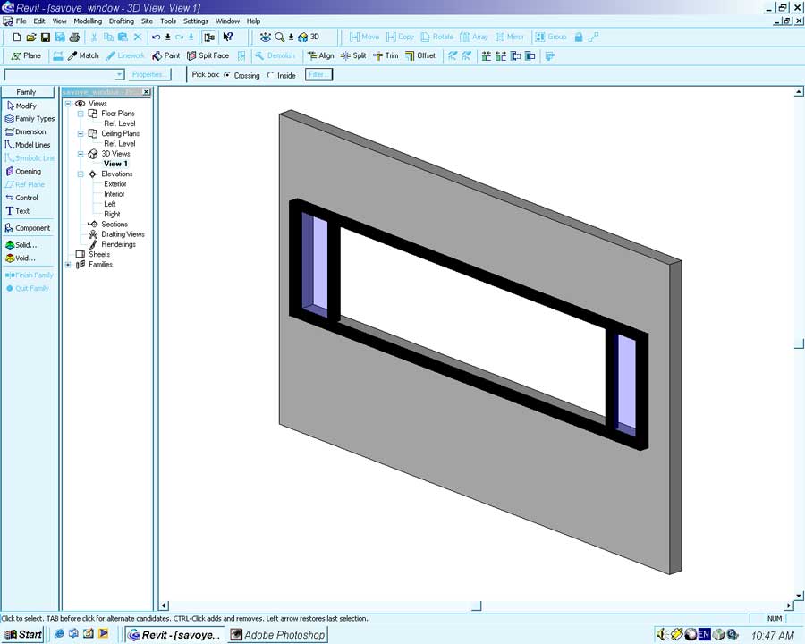
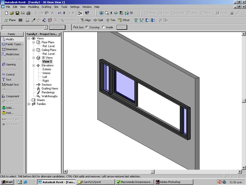
Open 3d View: View 1. You should have something like the following.
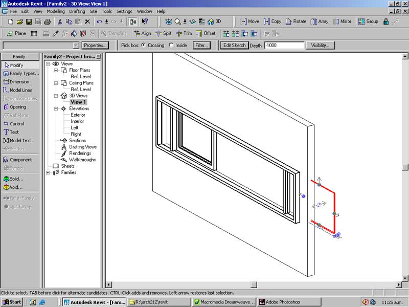
With the Modify tool select the new Extrusion.
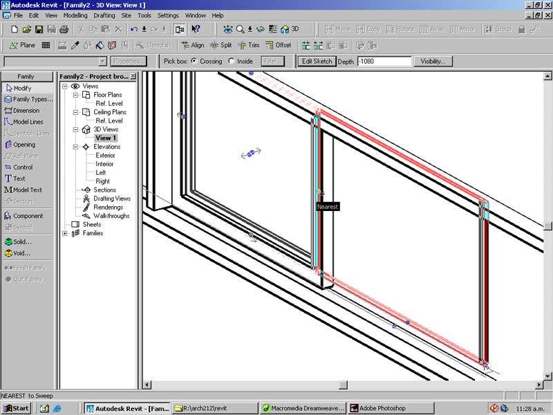
Drag the left and right arrows of the extrusion to position it within the window frame.
Revit should automatically snap to the inside of the frame but you will need to zoom your view in to ensure you are snapping to the correct point.
Once the glass is positioned you should have the following:
Make two copies of the frame and glass into the two frame bays.
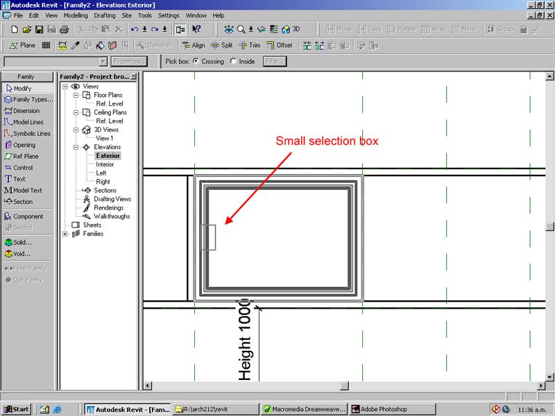
To do so open the Exterior Elevation view.
With the Modify tool drag a small box over a section of the frame and window.
From the menu select -> Edit -> Group so that both object can be selected as one.
Select the Array tool.
Click on the top-left corner of the frame and then on the top-left corner of the adjacent frame bays.
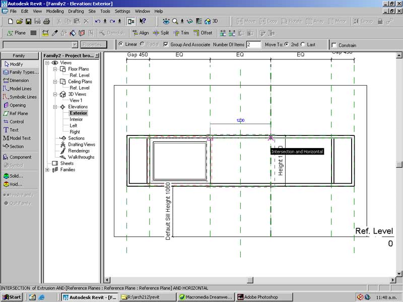
In the Number of copies box enter 3.
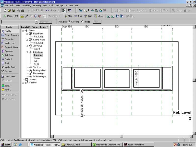
Select each of the frames and press the Ungroup button on the toolbar.
Once ungrouped select the middle frame and glass panel.
Open the Elevation: Left view and move the frame & glass 50mm to the left.
After completing these steps you should have a completed 3-dimensional window like the one shown below. It is possible to define unique geometry for this object in other views and levels of detail. Due to time constraints this tutorial will not cover this aspect of family creation.
From the menu select -> File -> Save
In the dialog browse to your project folder, give the window an appropriate name (such as Savoye Window) and save it.
Once saved close the window file and return to the tutorial project.
The Home Stretch
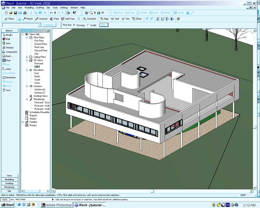
With the new window family created all that is left to do is place instances of it in the Villa Savoye model.
From the menu select -> File -> Load from Library -> Load Family...
Browse to the location of the saved window family and open the file.
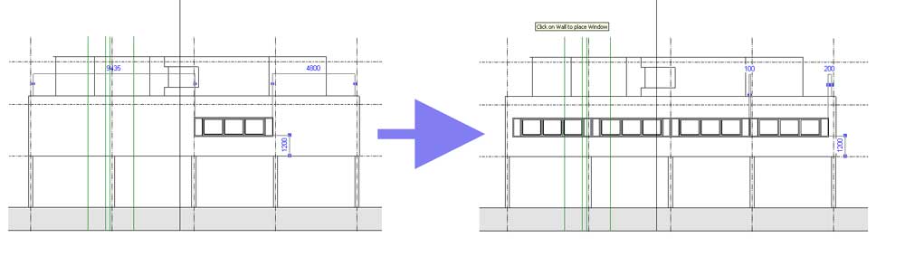
Open the South Elevation from the Project Browser.
Select the Window tool from the Basics or Modeling Sidebar.
In the Type dropdown select the 'Villa Savoye Window'.
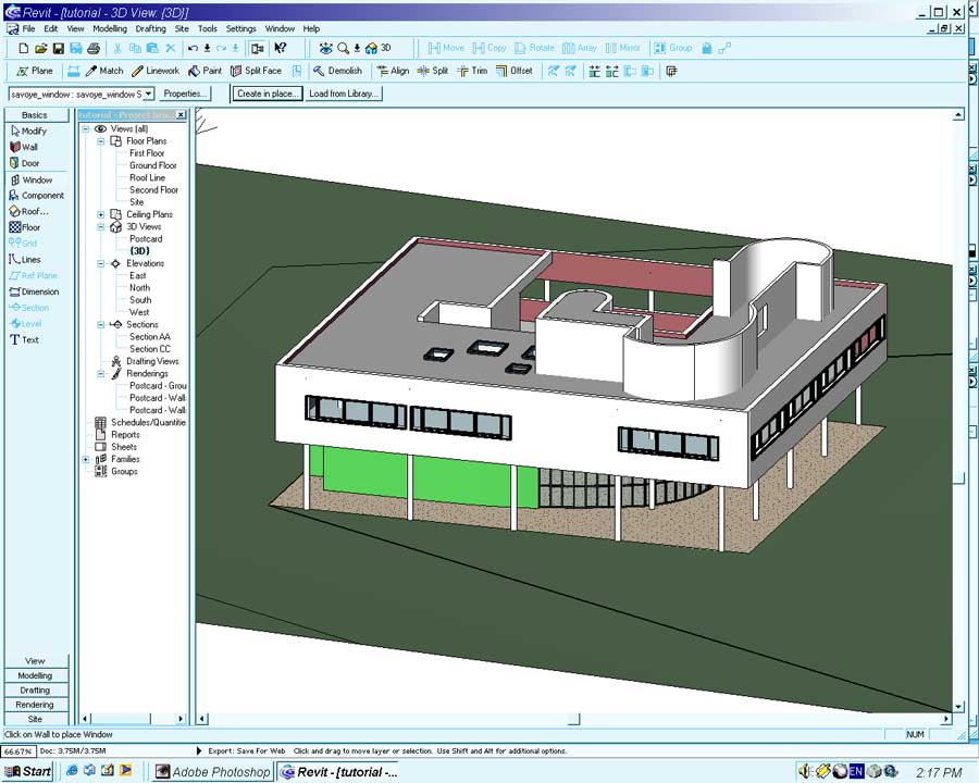
Starting from the building centerline place windows along the front facade.
Open the First Floor view and place a window in the southern bay of the east wall.
Place three windows in three of the bays in the west wall.
The remaining middle bay has a small window and a larger opening. We will achieve this by creating a new, smaller instance of the basic window.
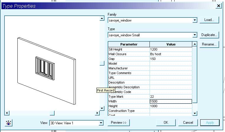
With the Window tool enabled press the Properties button in the toolbar.
In the Properties dialog select -> Edit/New -> Duplicate
Name: Savoye Window Small (Enter)
Set the Width parameter to 1500 and press OK.
In the First Floor view place the new, smaller window at the north end of the empty west wall bay.
In the Type dropdown select M_Opening: Villa Savoye First Floor.
Press the Properties button and in the dialog select -> Edit/New -> Duplicate.
Name: Villa Savoye West Opening (Enter)
Set the following properties for this new instance.
Sill Height: 1200
Height: 1000
Width: 2900
Press OK to create the new object.
In the First Floor view place the opening in the vacant space of the west wall as illustrated below.