In this section we will construct the basic form of the first floor and roof levels. By the end of this section the basic form of the Villa Savoye will have been achieved.
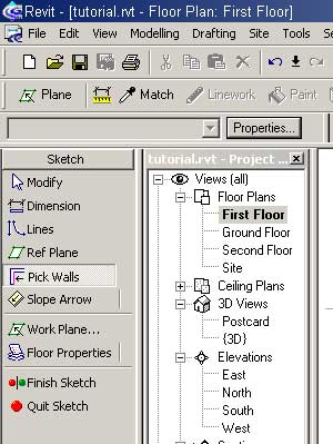
Open the First Floor view.
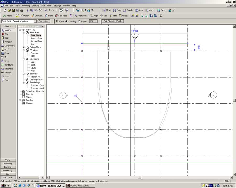
Place a horizontal Reference Plane inline with the outer edge of the northern most wall.
Select the Wall tool from the Basics Sidebar.
Set the following properties for the wall:
Type: Basic Wall: Generic 300mm
Location Line: Finish Face Exterior
Height: Second Floor
With these settings in place create a wall along the northern perimeter as shown below.
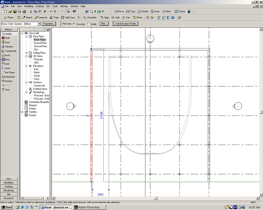
Set the Location Line to Core Centerline and place two more walls along the east and west perimeters of the first floor.
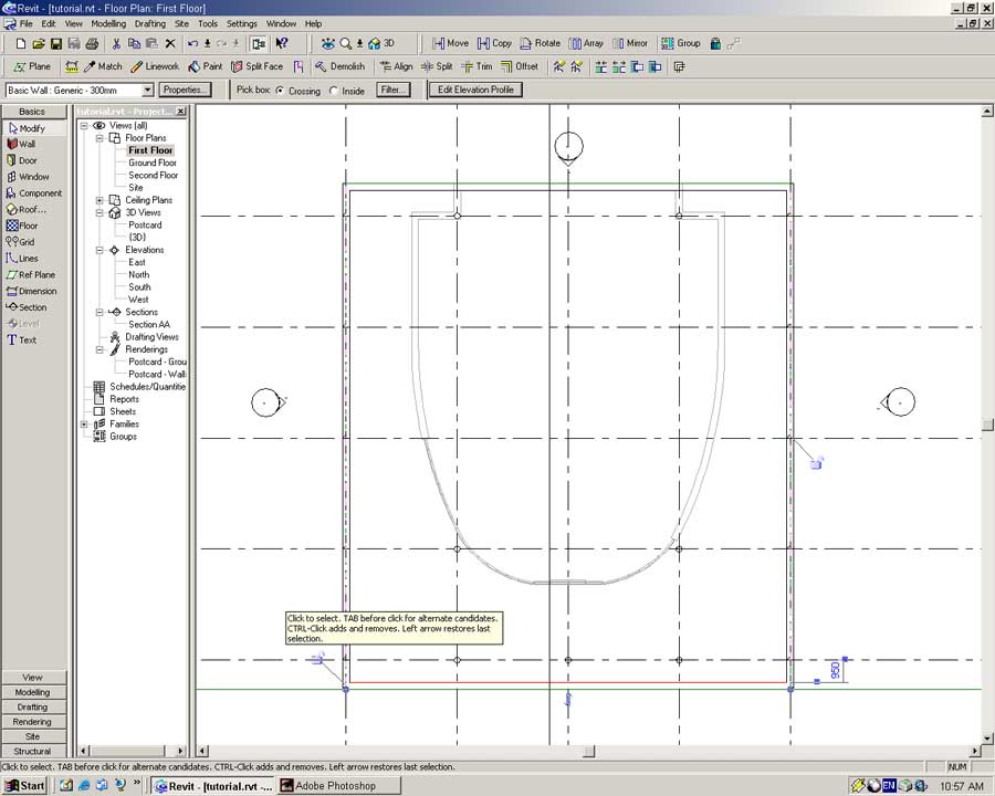
Set the Location Line to Finish Face Exterior and create a wall along the southern pad perimeter.
Ensure all the walls are orientated correctly as shown below.
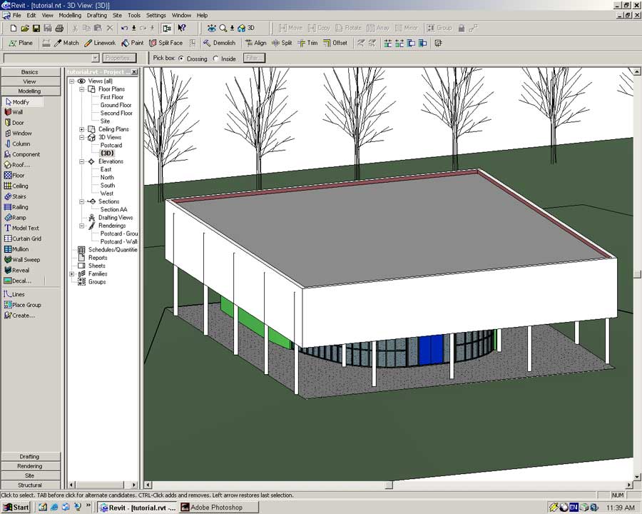
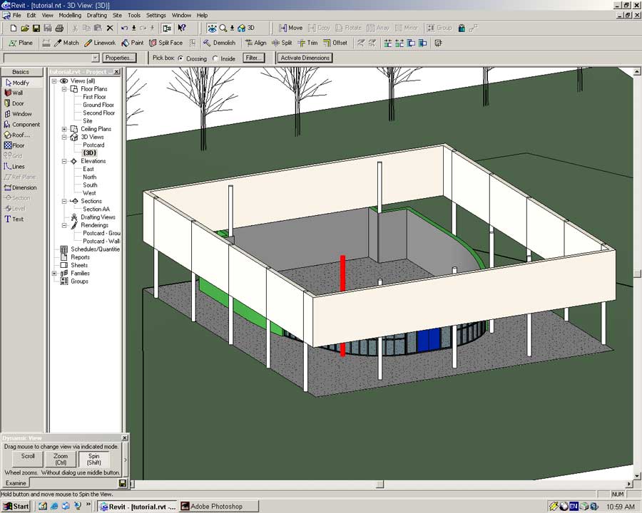
Open the {3D} view and take a look at what has been created.
You should note that the walls created extend from the First Floor level to the Second Floor Level. This is because the walls were constructed within the First Floor view.
With walls in place we will construct the floor slab and roof for the Villa.
Open the First Floor view.
From the Modeling Sidebar select the Floor tool.
Walls, drawn lines or a mixture of both can define the profile of a Floor object. In this example we will used the walls we just created to form the profile of the Floor Slab object.
Select the Pick Walls tool from the Sidebar and click on all four external First Floor walls.
Press the Floor Properties button to bring up the Properties dialog for the new floor.
Set the following properties:
Type: Insitu Concrete 225mm
Height Offset from Level: 225mm(This will place the base of the floor at the First Floor Level)
Press OK to accept the rest of the properties.
Select Finish Sketch to build the floor.
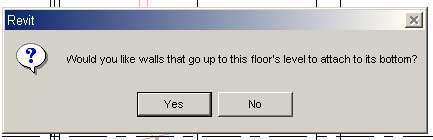
Revit will ask you whether the walls of the level below should connect to the base of the floor.
Answer Yes to this question to form a floor/wall relationship.
During creation of the floor the following error message will appear.
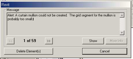
This is telling us the new floor slab intersects with the geometry of the curtain wall system below. In order to establish a relationship between floor and wall some of the mullions must be deleted. Select to Delete Element(s).
If you wish you can go back later and recreate the deleted mullions.
Open Section AA. If all has gone well you will see the following.
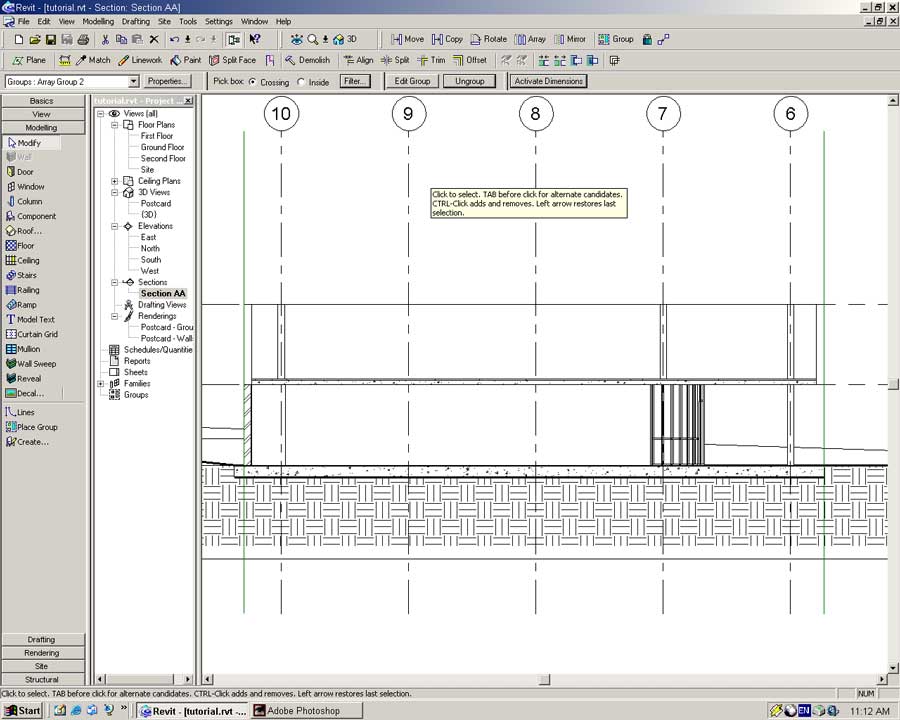
Notice the floor is inside the walls. This is the result of the Height Offset parameter.
With the floor in place we will move on to the roof.
Open the Second Floor level.
From the Modelling Sidebar select the Roof tool -> Roof by Footprint
Revit 5 has three means of creating a roof.
Roof by Extrusion builds a roof from a horizontal and vertical profile. Specifying a footprint builds creates a roof from a footprint and angles of roof pitch.
Roof by extrusion is good for unique roof shapes that do not conform to conventional roof forms. In this tutorial we will define a roof through specifying a footprint.
Roof Soffit is the underside of a roof and is used to add thickness to an exisiting (pitched) roof.
Extrusions, soffits, facia and gutters are all easily achievable in Revit 5. Check the online help for instructions.
As with the Floor object we will use the First Floor walls as the basis for the roof.
Select the Pick Walls tool from the Sidebar and select the internal faces of the external walls.
Press the Roof Properties button in the Sidebar.
In the dialog set the Type to Cold Roof - Concrete and press OK.
Click the Finish Roof button in the Sidebar to build the roof.
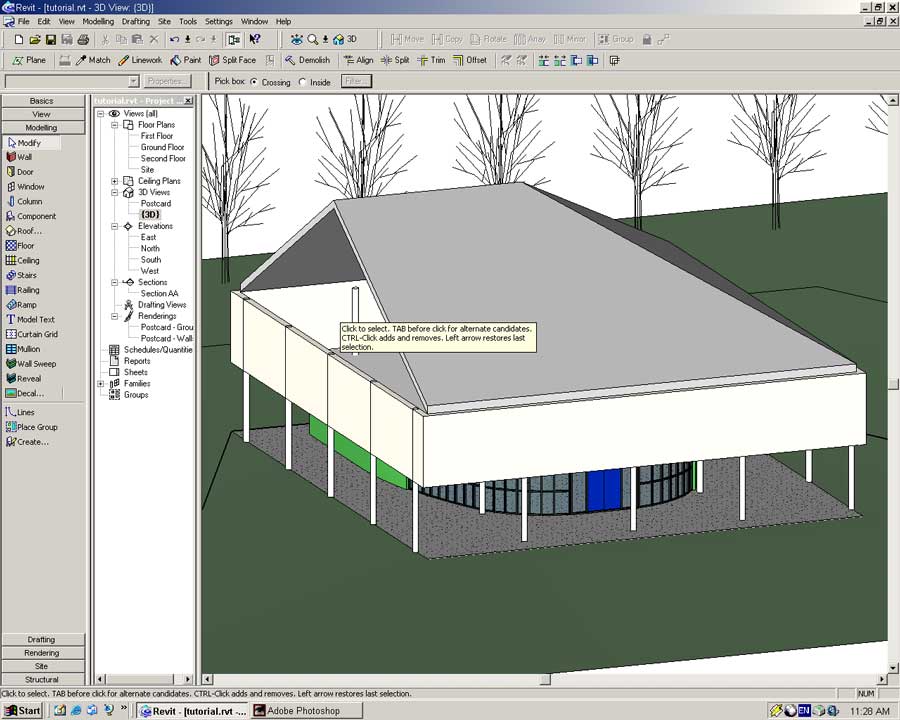
Open the {3D} view.
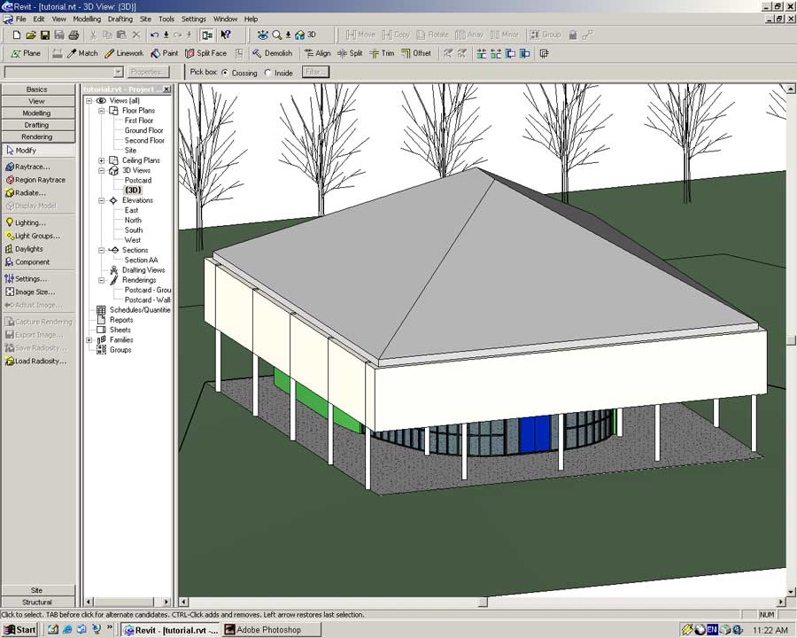
He hee. I did that just for fun. By default Revit makes nice little pitched roves.
But we do not want a pitched roof. Go back to the Second Floor view.
With the Modify tool enabled select the Roof object. Press the Edit Sketch button in the toolbar.
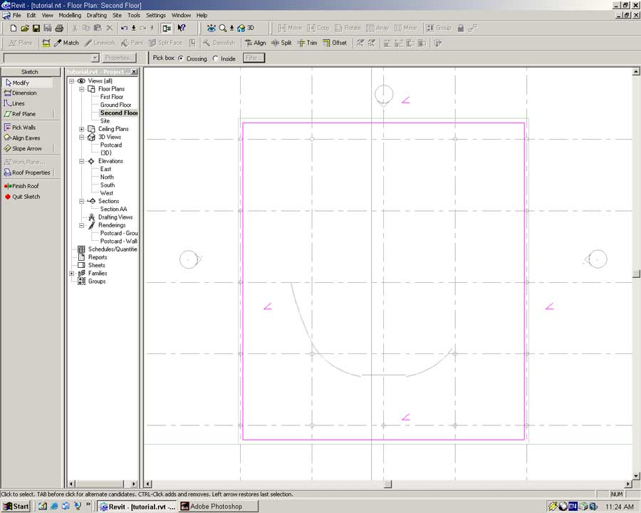
The angle symbol by each of the roof footprint lines indicates a sloped roof base-point.
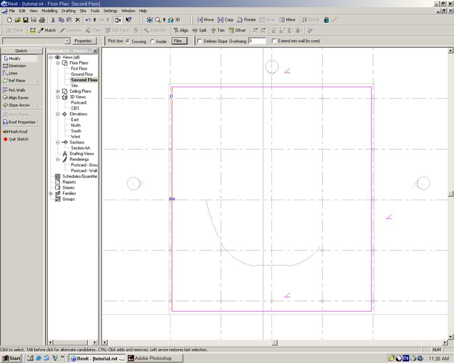
With the Modify tool select a footprint line and uncheck Defines Slope in the toolbar.
For a bit more fun press Finish Roof, open {3D} view and see what you get.
Somehow I do not think that is what Le Corbusier wanted when he designed the Villa Savoye.
Go back to the Second Floor view and modify the roof.
Remove all the slope definitions from each of the footprint lines and press Finish Roof.
Switch to {3D} view to see what you have.
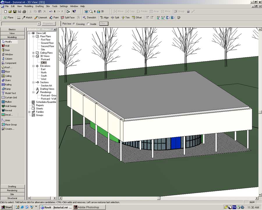
You will notice the walls do not meet the roof. We will fix that by defining a new wall type.
With the Modify tool enabled select all the First Floor exterior walls and press the Properties button.
In the dialog set the Type to Villa Savoye Ground Floor and press Edit/New -> Duplicate
Name: Villa Savoye First Floor (Enter)
Edit the Structure of the Wall object.
In the structure dialog enter the following settings:
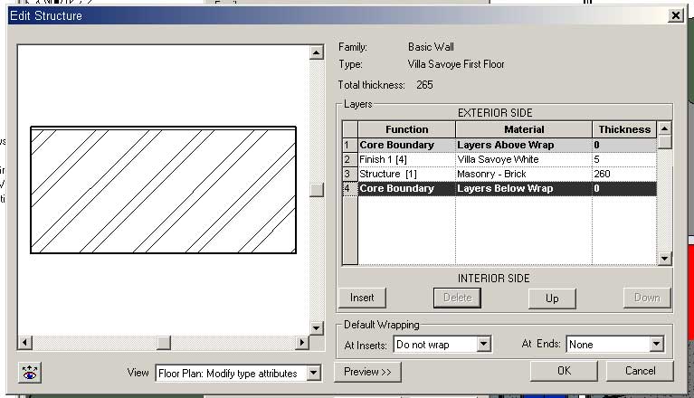
Press OK in the Type Properties dialog.
In the Element Properties set the Top Offset to 500mm and press OK.