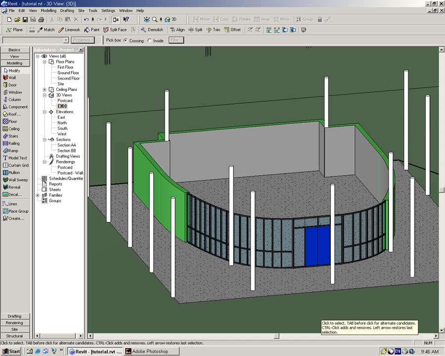
Now we have the site, structure and the ability to explore and render we should really construct the building.
Open the Ground Floor view. In the drawing window right-click and select View Properties from the popup menu.
In the Visibility field press the Edit button.
The following dialog will open.
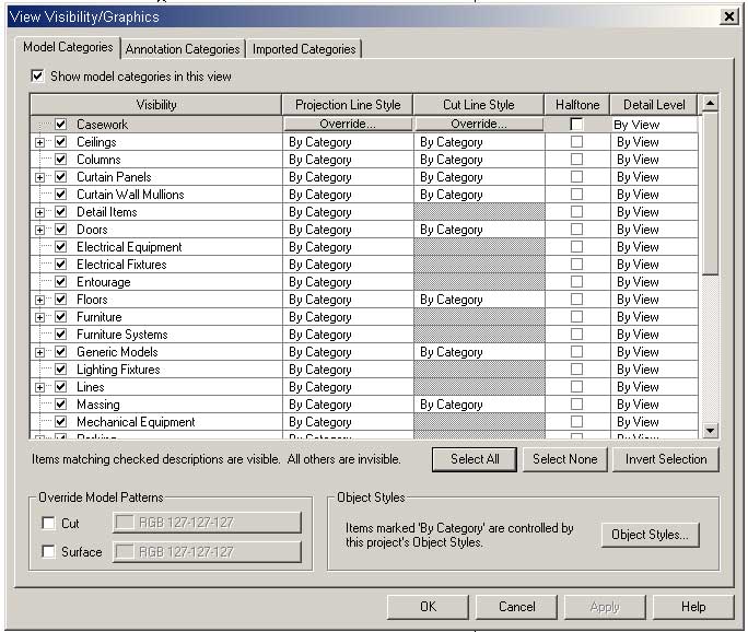
The Visibility dialog enables us to control what is visible in a particular view. Those familiar with AutoCAD will find this familiar to the Layers dialog box. The difference with Revit is that visibility is controlled on an object basis rather than by layer.
To make our modeling life easier we will temporarily hide the structural grid lines.
Open the Annotation Categories tab and uncheck the Grids option.
Press OK twice to close the Visibility and View Properties dialogs.
You will notice the view no longer shows the structural grid lines.
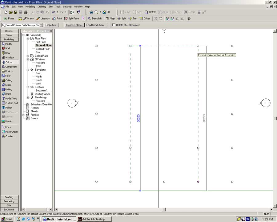
From the Modelling Sidebar select the Column tool .
In the Type dropdown select Concrete_round_M: Villa Savoye Column.
Place two columns at the points indicated below.
Ensure when placing the columns they snap to the underlying structural grid layout.
Select both columns. Change their height property to extend to the Second level just like the other columns.
With all of the columns in place we will construct the ground floor walls.
Make the structural grid visible again by right-clicking on the drawing window and selecting -> View Properties -> Visibility -> Edit -> Annotation Categories and ticking the Grids option.
Select the Wall tool from the Basic or Modeling Sidebar.
The Generic Wall 300mm thick will do for now. Later we will define a Villa Savoye wall object for use in this model.
Set the Height dropdown to First Floor and the Location Line to Wall Centerline.
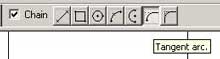
Tick the Chain option to create a continuous series of walls linked together.
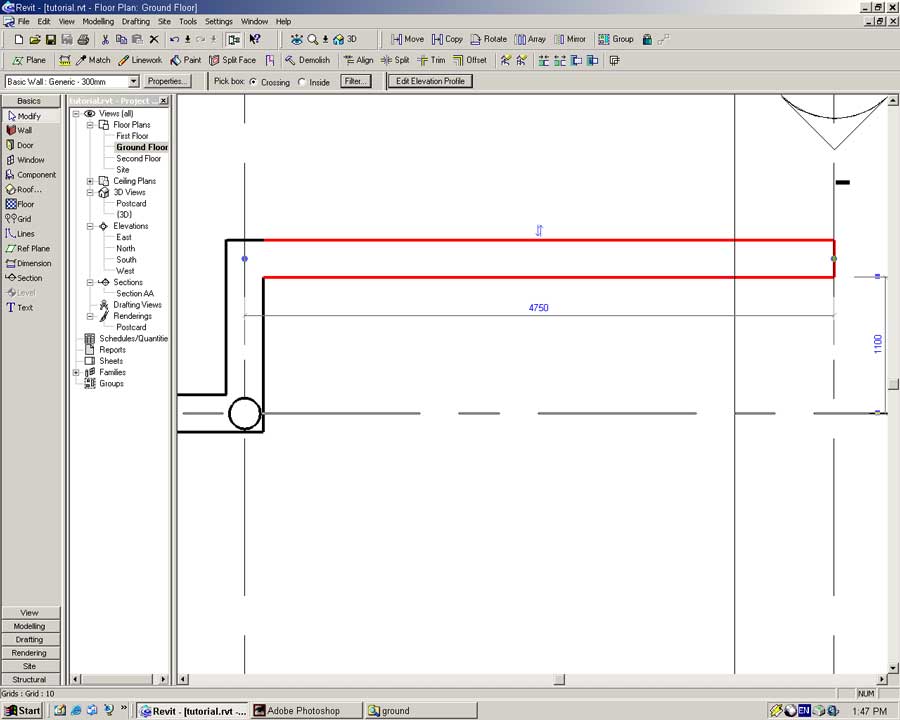
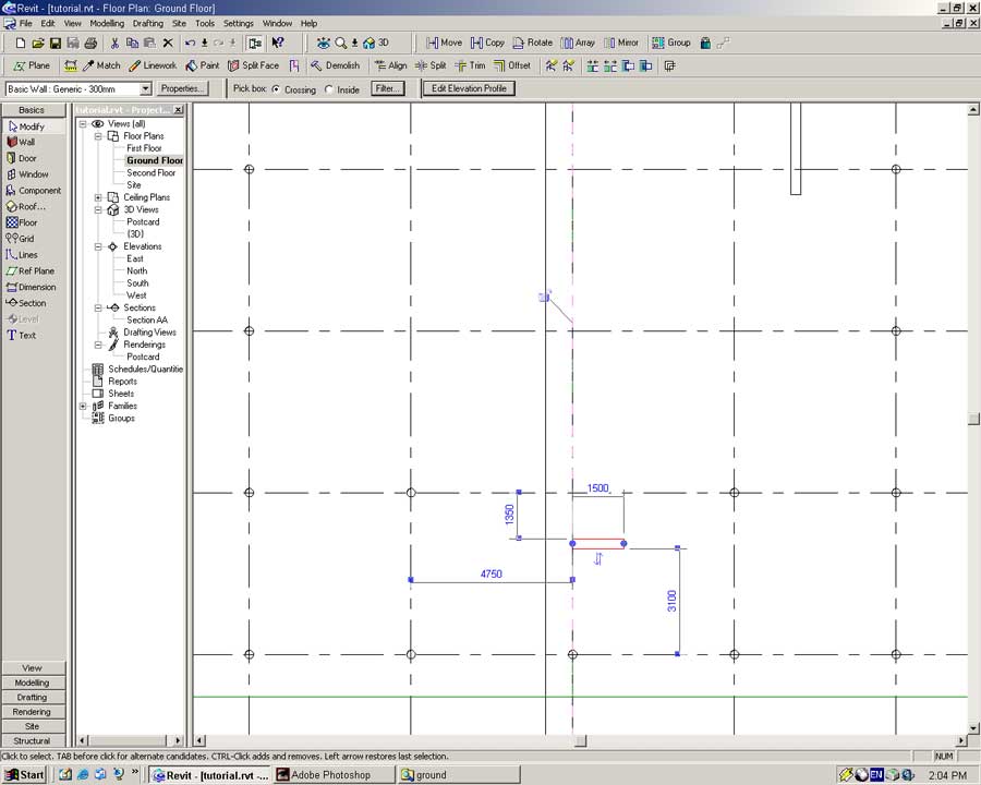
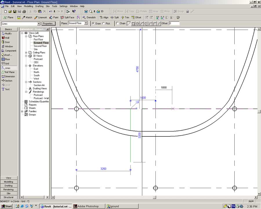
Begin the wall from the point below. Left-click once to start placing the wall.
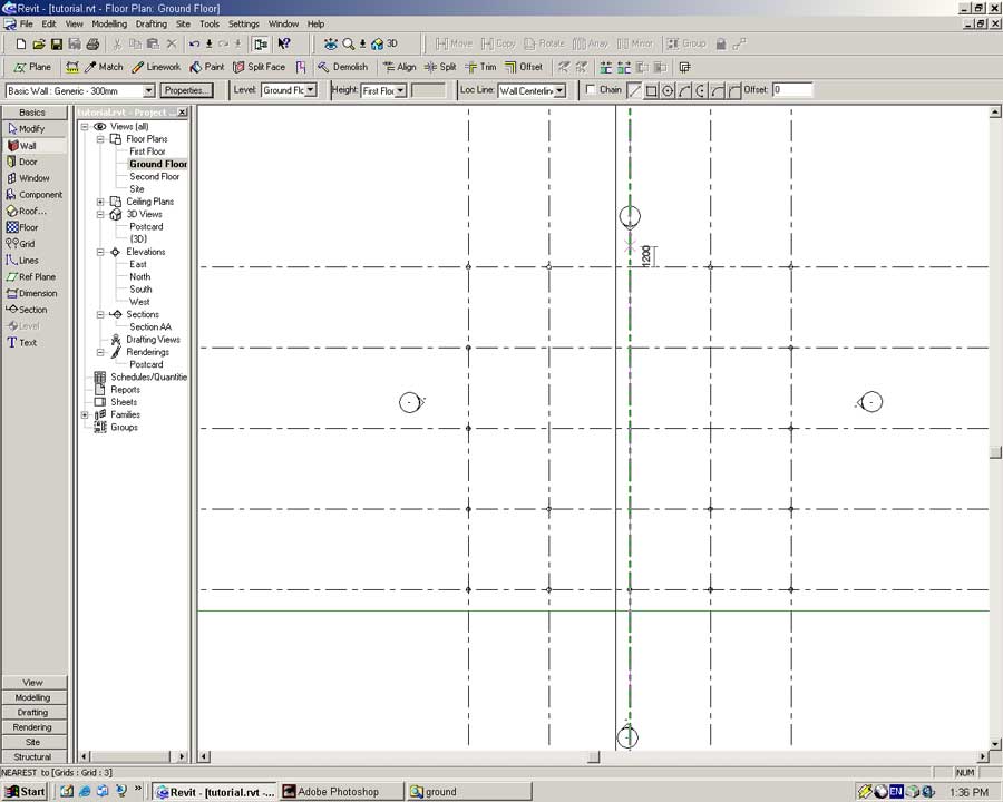
Move the pointer to the left until the dimension line reads 4750mm and left-click once to place the wall.
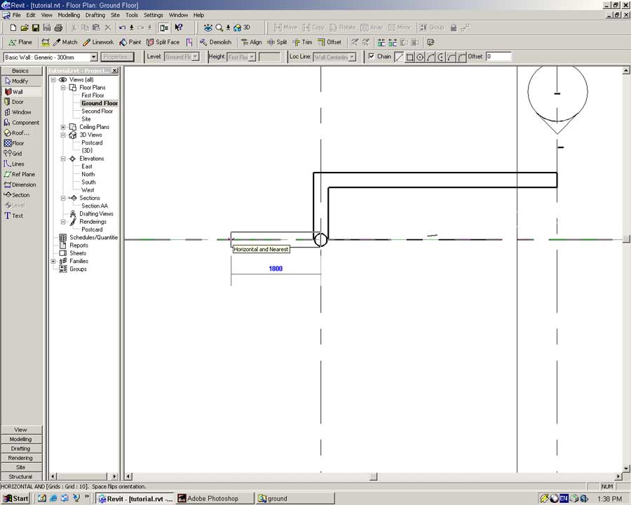
Using one of the zoom tools enlarge the view and place the next wall end-point on the center point of the structural column.
Move the pointer to the left until the dimension line reads 1800mm.
Left-click once more to place the final piece of wall. You should have something similar to the following:
Right-click in the drawing window, from the popup menu select Cancel to stop placing walls.
Walls in Revit have exterior and interior facings. When we place walls we must ensure they are facing the correct way.
Using the Modify tool select the first piece of wall that was created. The up/down arrow at the center of the wall indicates the exterior face of the wall. It is quite likely the wall is orientated the wrong way as shown below.
If the walls in your model are orientated the wrong way click on the up/down arrow to flip the orientation of the wall.
Check the orientation for the other wall elements.
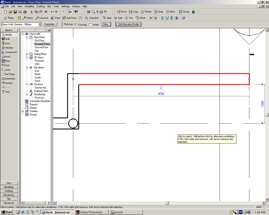
With that bit of housekeeping out of the way we will modify the length of the first piece of wall we placed.
Select the first piece of wall we created using the Modify tool.
In the vertical distance from the horizontal structural grid type 1100 (Enter)
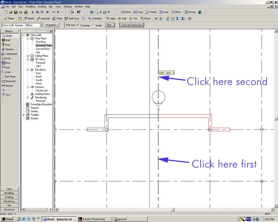
To create the other half of the northern wall we will mirror the wall we have created along a vertical mirror line.
Select the three wall segments with the Modify tool. Remember to hold the CTRL key down to select more than one element.
In the toolbar select the Mirror tool.
Click on the points indicated below to mirror the walls.
Open the {3D} and Postcard views to check out what you have built so far.
Switch back to the Ground Floor view and construct a wall 5500 long from the end of the newly mirrored wall.
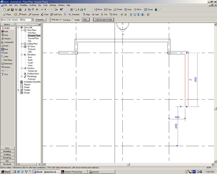
We will now begin to construct the front door.
Place a wall at the point indicated to a point 1500 horizontally to the right. Ensure it is orientated in correctly.
You should have the following:
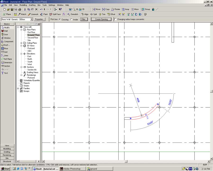
From the end of this wall create a new wall using the Tangent Arc line option.
Begin from the end centerline of the new wall. Make the end of the wall snap to the gridline with an angle of approximately 75o as shown below.
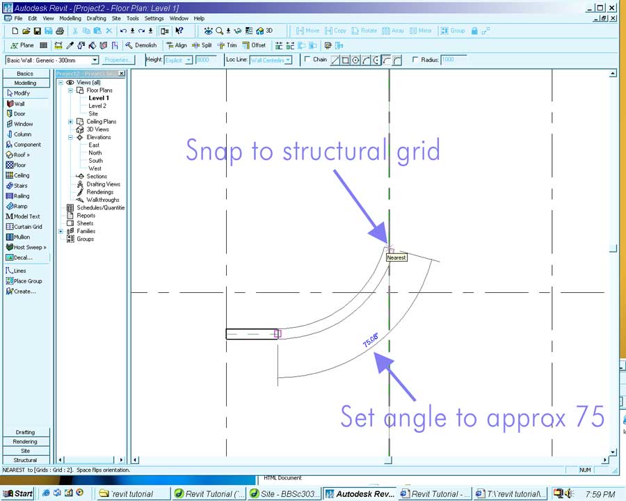
With this wall placed stop wall creation by right-clicking and selecting Cancel.
Select the wall with the Modify tool.
Set the radius of the wall to be 4500mm and the arc to 55o. You should have the following:
Using the Tangent Arc option of the Wall tool, connect the separate pieces of the ground floor as illustrated below. (HINT: Start at the straight piece of wall and make your way to the curved segment.)
The resulting arc is not perfect in relation to the real Villa Savoye. Feel free to play around with it if you want, but for the purposes of this tutorial it will do nicely.
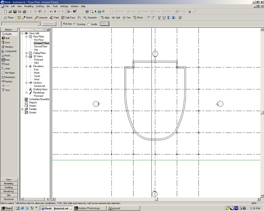
With the Modify tool select all the new pieces of the ground floor.
Mirror these walls using the Mirror tool. Place the mirror line along the vertical center axis.
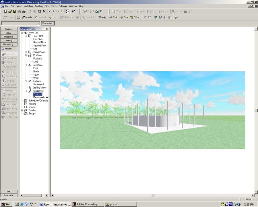
Just for fun render the model.
Open the Postcard view. From the Rendering Sidebar select the Raytrace tool and press the Restart button.
A portion of the wall we just created is a glazed curtain wall. In this section we will build this curtain wall.
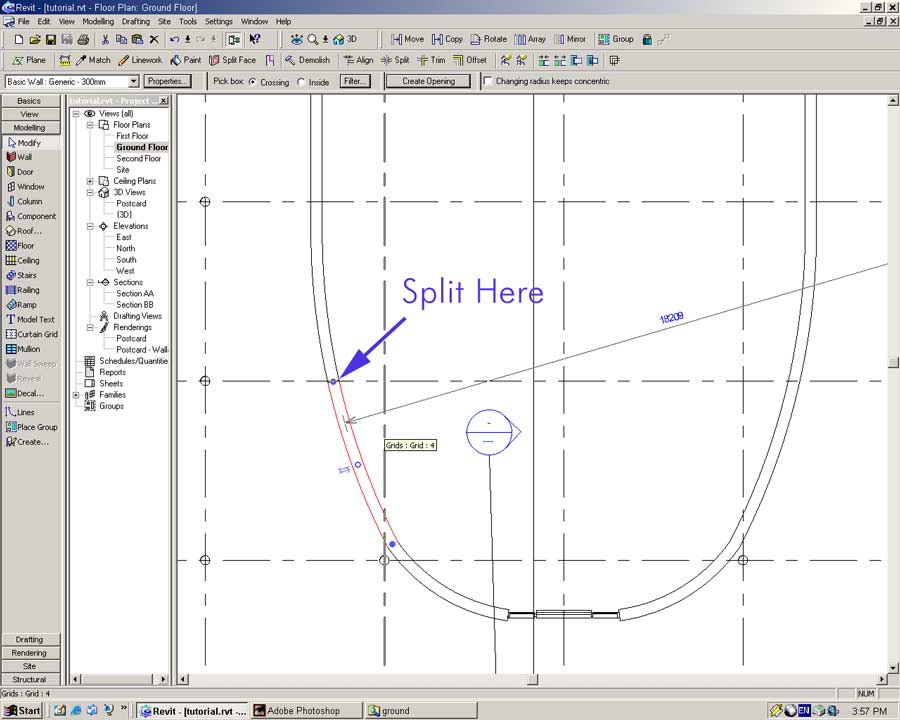
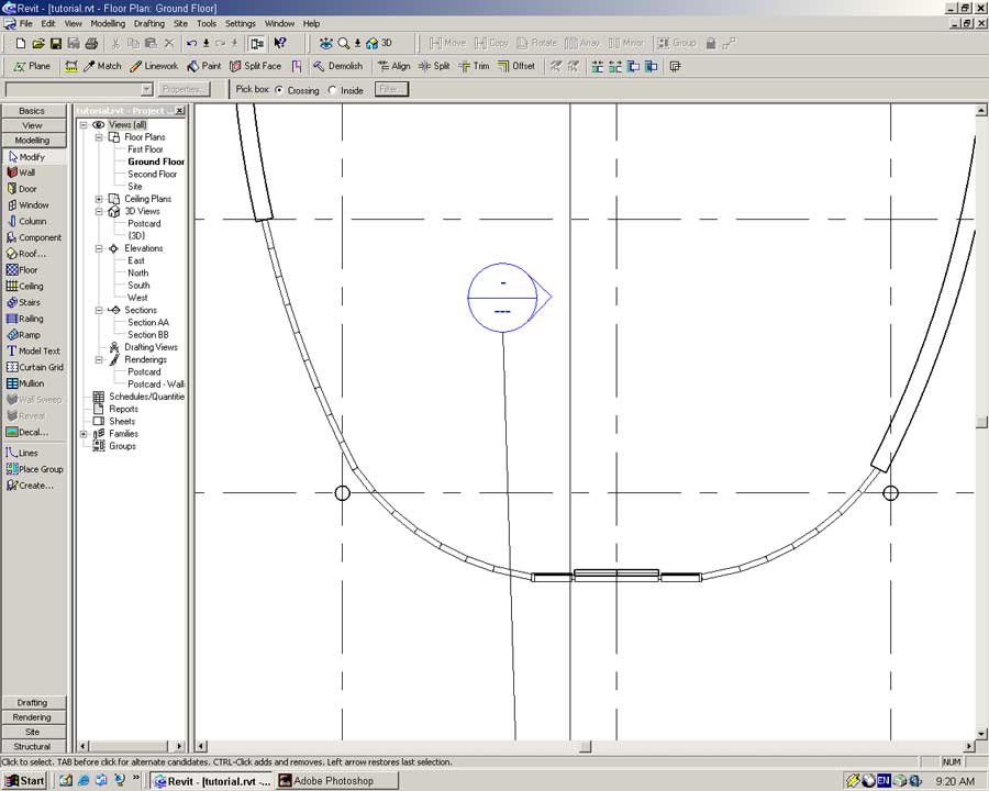
Open the Ground Floor view. Using the Lines tool from the Basics Sidebar place a line object 1500mm from the centerline as illustrated below.
Select the Split tool from the toolbar.
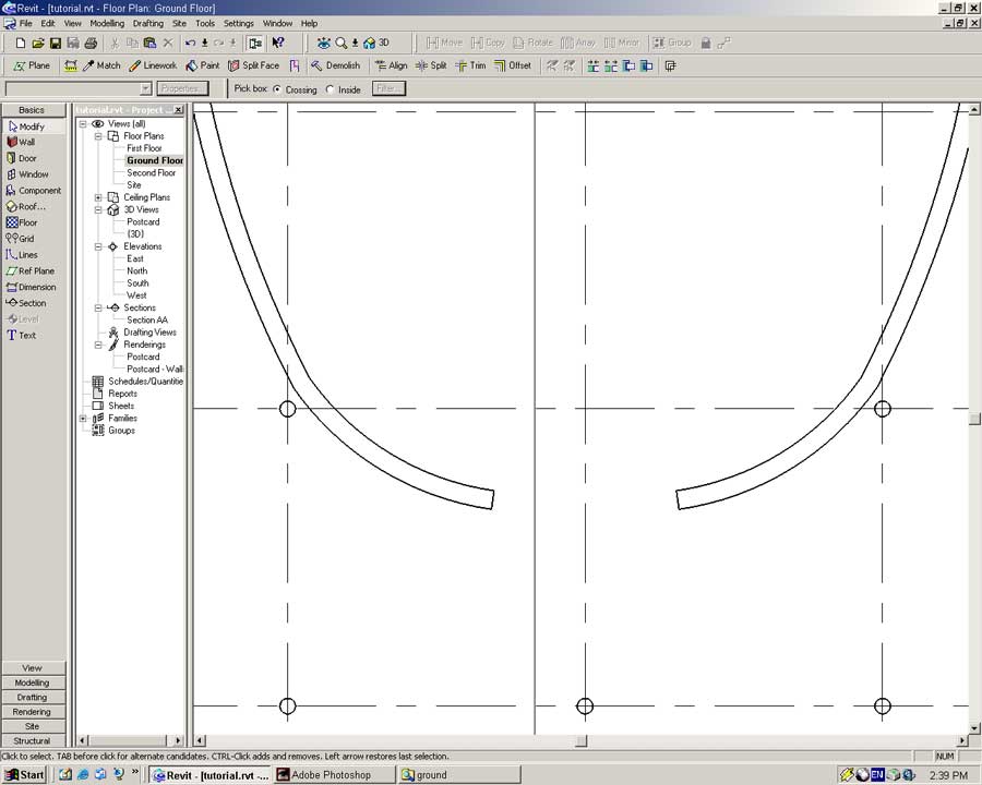
Using the line as a guide split the geometry of the curved wall.
Repeat the above process for the right-hand side of the door.
Once split, delete the two pieces of wall as indicated below by selecting each segment and pressing the Delete key.
From the Basics or Modeling Sidebar select the Wall tool.
In the Type dropdown select Curtain Wall: Curtain Wall 1.
Press the Properties button to bring up the Properties dialog.
Select Type -> Edit/New -> Duplicate
In the Name field type: Villa Savoye (Enter)
Set the Wall Function field to exterior and press OK to close the Properties dialog.
Place the wall at the end of the curved wall. Click on the centerline of this wall to begin placing the object.
Move the pointer horizontally to the centerline and click to build the wall.
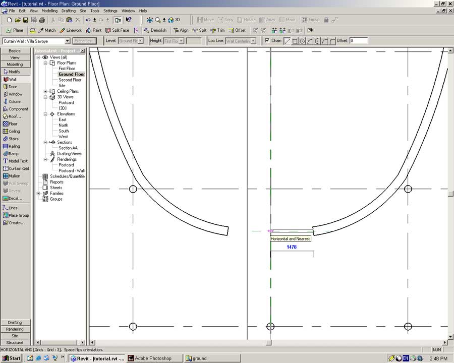
Place another Curtain Wall from the end of the opposing curved wall to the centerline.
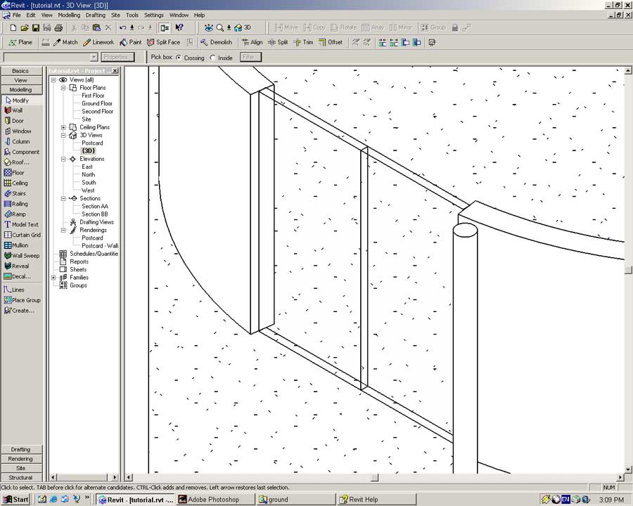
Switch to {3D} view. The model should look like the following.
A Curtain Wall object is merely a placeholder for a series of mullions and panels. To complete construction of the curtain wall we must define the location of the Mullion and Panel objects.
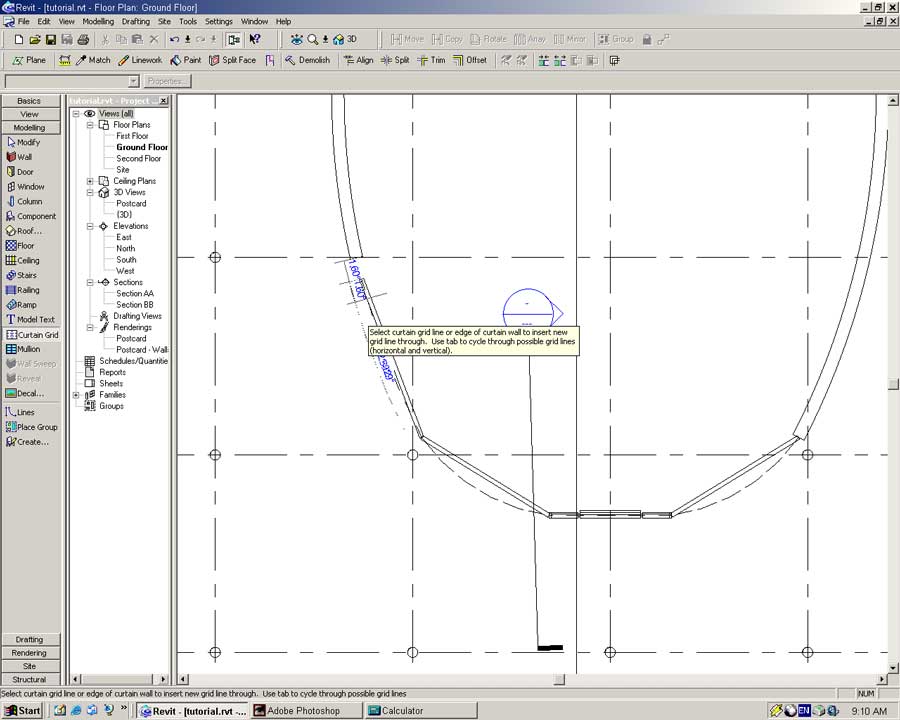
In the Modeling Sidebar select the Curtain Grid tool.
Place a vertical gridline in the middle of both wall segments as shown below.
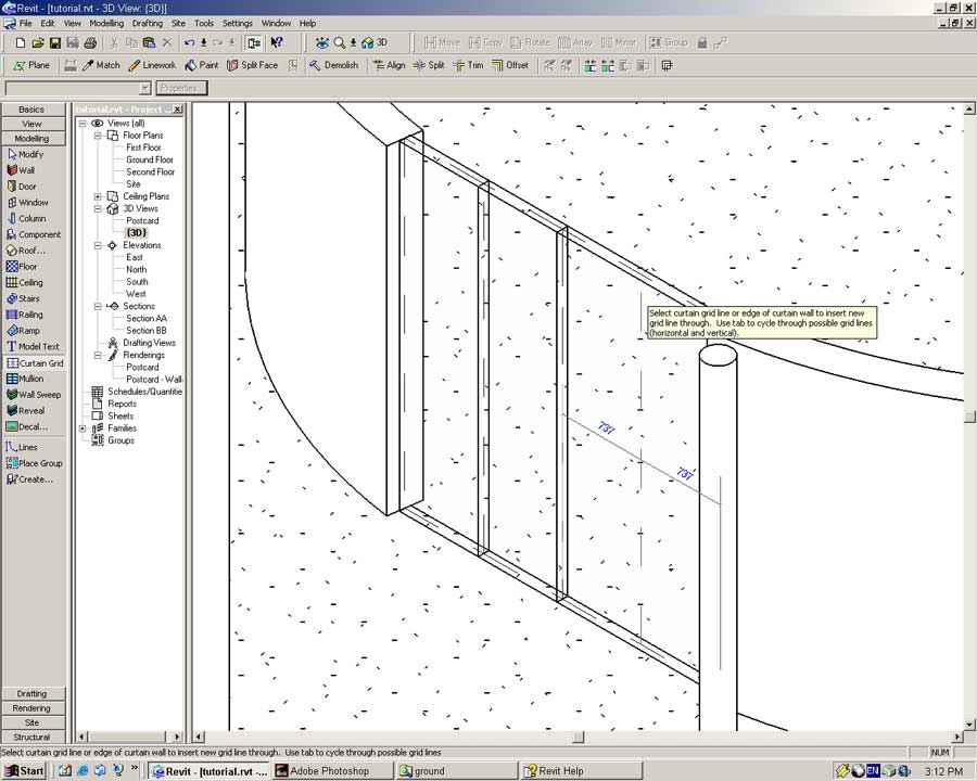
Using the Modify tool select the mullion gridline (a dashed line).
To do so place the pointer over the gridline and press the TAB key until the gridline is selected.
Set the distance from the center of the door to the vertical gridline to be 750.
Be patient, this can be a little tricky!
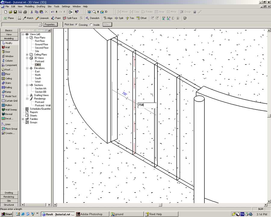
Repeat this step for the mullion grid on the other side of the centreline.
This creates two 750mm wide spaces for the front double doors.
In both Curtain Wall objects place horizontal gridlines 2400 from the ground.
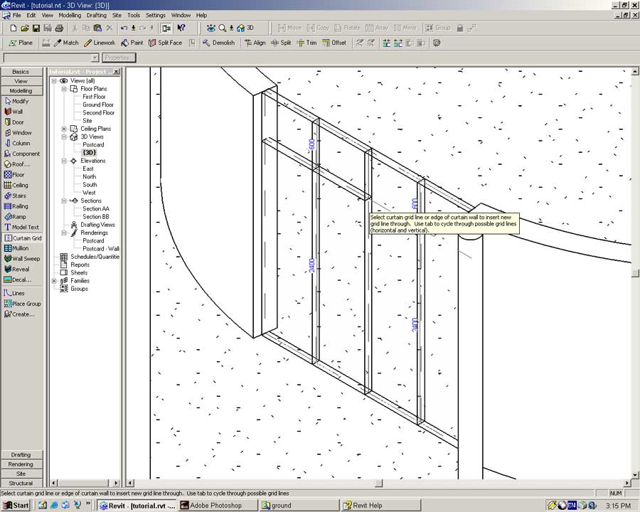
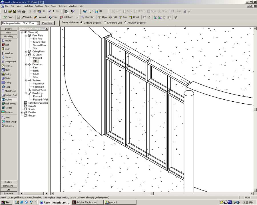
Now that we have a framework of gridlines established within the Curtain Wall objects we are able to place the mullions.
From the Modelling Sidebar select the Mullion tool.
In the Type dropdown select Rectangular Mullion: 50x150mm
Place a Mullion objects on the outer vertical gridlines within the Curtain Wall object.
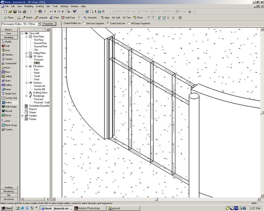
Repeat for the horizontal gridlines.
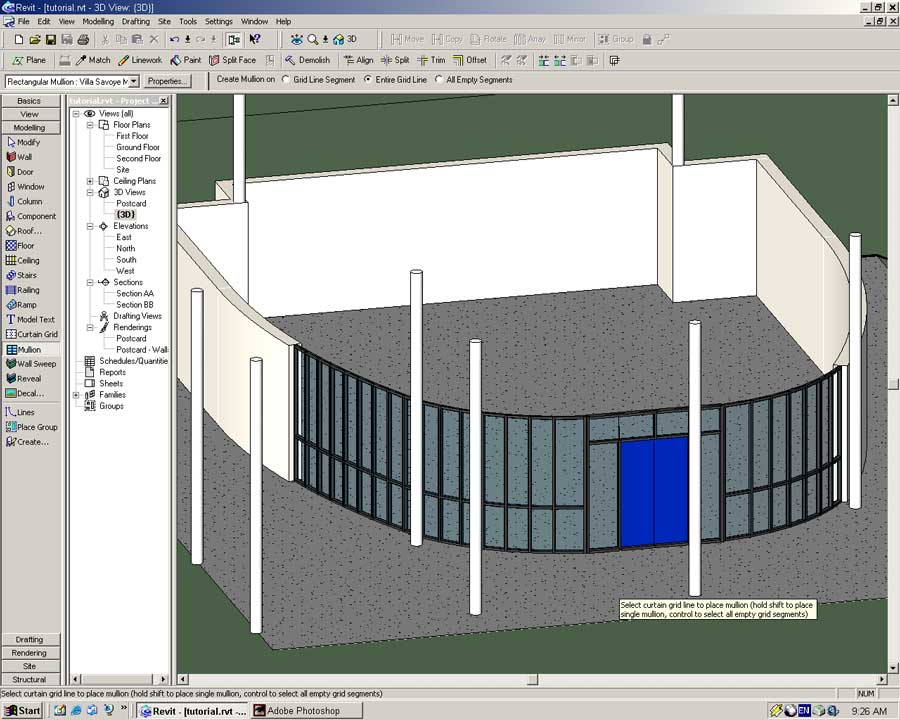
In the Mullion options toolbar select the 'Create Mullion on Gridline Segment' and place a mullion at the top center gridline as shown below.
With our Mullion objects placed we will create curtain wall panels for our Curtain Wall. Before we can do this we may need to load a couple of Panel families.
From the menu select -> File -> Load from Library -> Load Family...
In the dialog browse to Metric Library ->Components -> 46 Glazing ->4611 Curtain Wall Panels -> Curtain Wall Panel-Solid (M).rfa and open the file
In order to be able to place Panel objects we need to hide Wall and Mullion objects in the current view. It is possible to place Panel objects with these objects visible but it is frustrating!.
In the dialog select -> Visibility -> Edit
Uncheck Walls and Curtain Wall Mullions.
Press OK in both dialog boxes to accept the changes.
In the toolbar press the Hide/Isolate button (it looks like a pair of glasses).
This tool lets us selectively hide objects in view quickly.
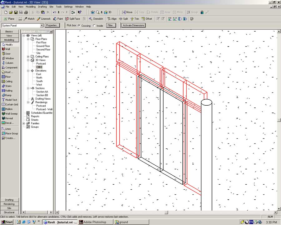
Drag a selection box over the entire door area. The box can be as large as you like.
Press the Filter... button in the toolbar.
In the popup window uncheck Curtain Panels and press OK.
In the Temporary Hide/Isolate floating pallete press the Hide Selected button.
Everything but the Curtain Panels in the view will disappear.
Close the Hide/Isolate floating pallete by pressing the close button in the corner of its pallete window.
Select the panels in red shown below,
In the Type dropdown select M_Glazed Panel: Glazed Panel as their type.
Select the two large door panels highlighted below.
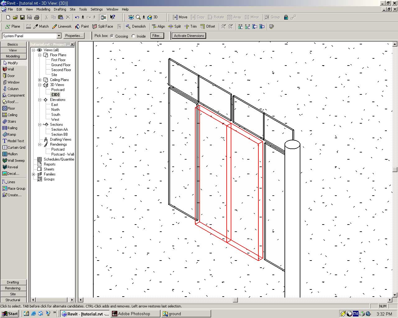
Set their type to M_Solid Panel: Solid Panel
The doors in the Villa Savoye photographs are a bold purple colour. We will create this finish for the doors in this model.
From the menu select -> Settings -> Materials -> Duplicate
In the name field type: Villa Savoye Doors (Enter)
Select a nice purple colour for the doors. If you want you should also define a purple AccuRender material. If you do not define an AccuRender material the doors will be a flat grey when raytracing is performed.
Using the Modify tool select both door panels (hold the CTRL key down). Bring up their properties.
In the Properties dialog select -> Edit/New -> Duplicate
Name: Villa Savoye Door (Enter)
Set the Finish to Villa Savoye Doors and press OK.
We will now define a black steel material for the mullions.
From the menu select -> Settings -> Materials -> Duplicate
Name the material Black Steel. Choose an appropriate colour and AccuRender material and press OK.
Press the Hide/Isolate button and select Reset from the floating pallete to make all the geometry visible.
Using the Modify tool select the perimeter mullions. Bring up their properties.
In the dialog under Type select -> Edit/New -> Duplicate
Name: Villa Savoye Door Mullions (Enter)
Set the Material field to Black Steel and press OK.
Select by dragging a large selection box and using the Filter... tool to select only the Curtain Wall Mullions.
View their properties by pressing the Properties button.
In the dialog under Type select -> Edit/New -> Duplicate
Name: Villa Savoye Mullions (Enter)
Set the Material field to Black Steel, Thickness to 70 and press OK.
You should have the following:
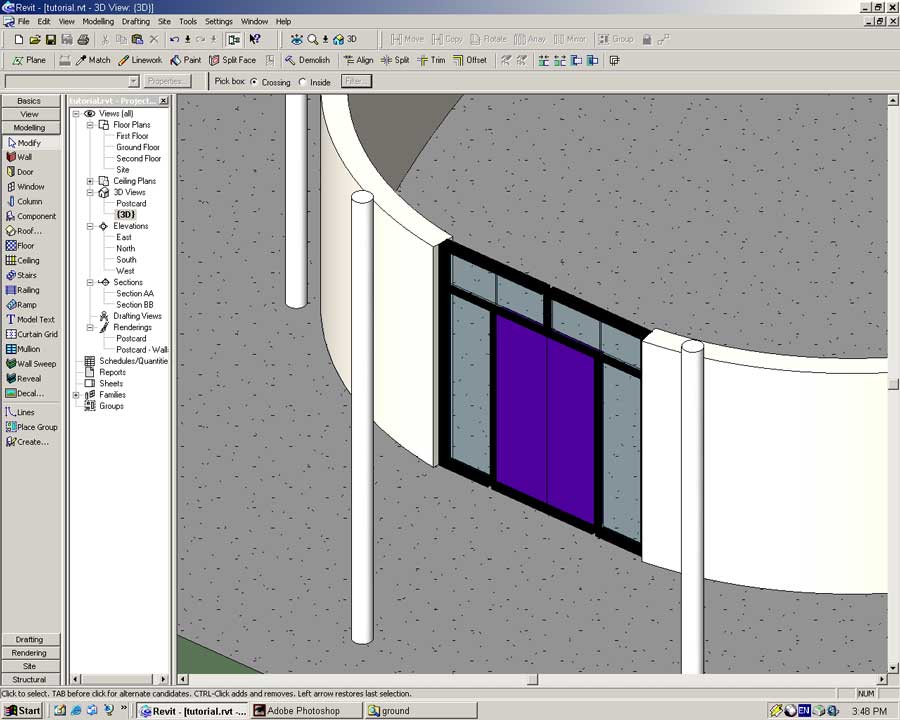
This tutorial will only develop the doors this far. If you wanted feel free to add the door step, handles and any other features you like. For now we are going to move onto the curtain walls surrounding the doors. Before we move you may want to complete a rendering in order to admire your handiwork.
The Glazed Entrance
When you have finished split the left hand curved wall at the intersection shown below:
Select the three wall sections south of the split and change their type to Curtain Wall: Villa Savoye.
You may notice one of the walls may not touch the adjacent walls anymore.
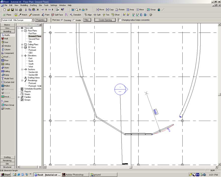
To fix this drag the blue dot that is touching the existing wall back into contact with the curtain wall.
Now move the arc back to the old wall centerline.
Ta dah! Hopefully your new curtain wall now extends to the existing walls.
You will notice the Curtain Wall objects are straight and do not follow the defined curve. A limitation of a Panel object is that is must be in a single directional plane. In order to follow the curve we must add mullions to break up the panel.
The Villa Savoye has mullions spaced 500mm apart. When dealing with angles we cannot measure in linear distance, only angular distance. What do we do? (If you are in a classroom put your hand up now.)
Yes that is right, we calculate the angular dimension of the linear distance using the formula 2R to determine the perimeter of the entire circle. We then find what percentage 500mm is of the entire perimeter and multiply this result by 360o in order to get that percentage as a degree. (Whew) You all knew that right?
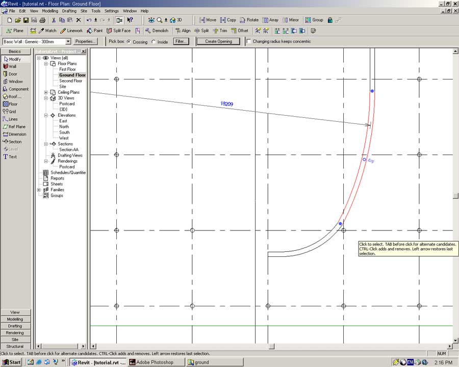
To help you out I will tell you the answers, for the curtain wall with a radius of approximately 18200mm the angular distance in order to achieve a linear spacing of 500mm is approximately 1.6o. For the other smaller wall sections an angular distance of approximately 6.4o should achieve 500mm spacing.
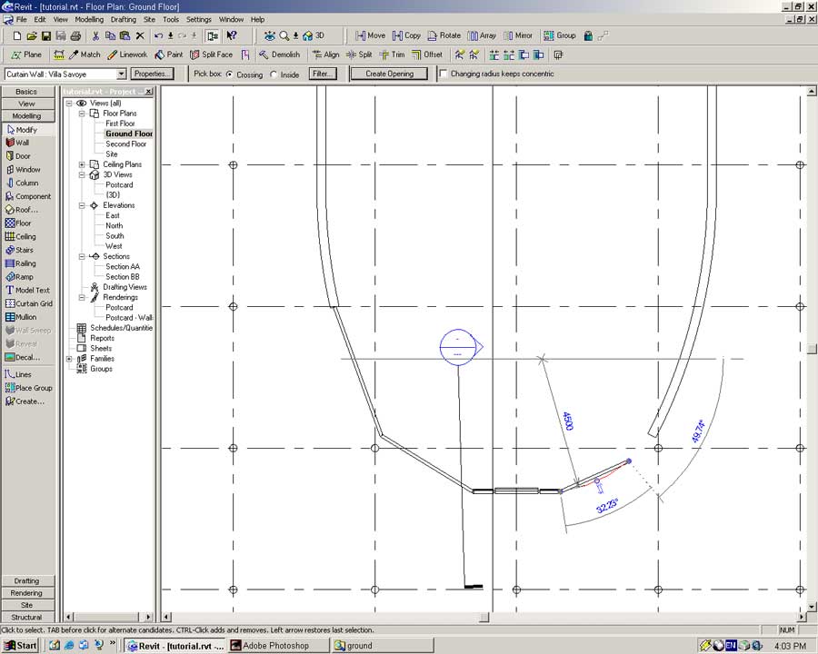
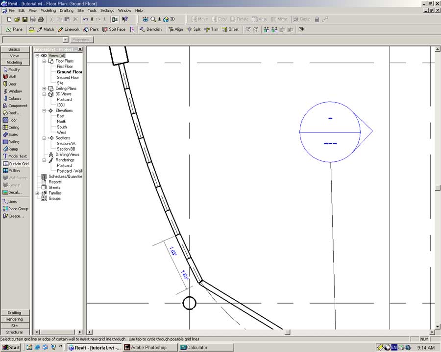
Zoom into the larger curved wall and add mullions at 1.6o intervals.
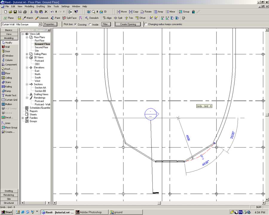
Repeat down the length of the first wall segment to achieve the following result.
Repeat the entire process for the other two walls. Remember to use an angular distance of 6.4o.
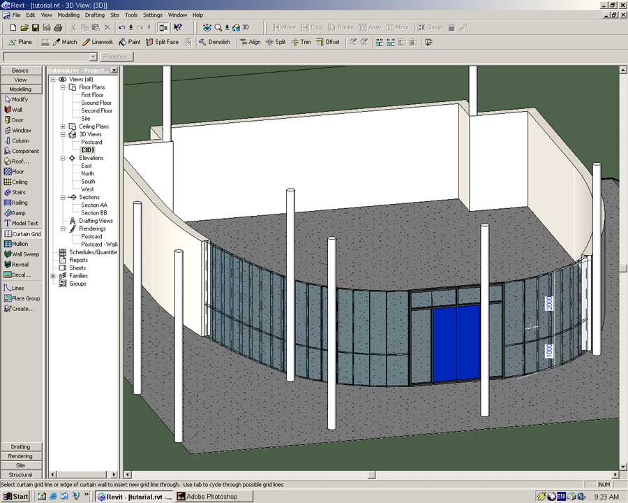
Switch to {3D} view and find yourself a good view of the curtain wall.
Place a horizontal mullion gridline 1000mm from the ground in each of the sections.
Using the Mullion tool from the Modeling Sidebar place Rectangular Mullion: Villa Savoye Mullions on all of the gridlines as shown below. A shortcut in doing this is to hold the CTRL key down and clicking the curtain wall. Mullions will be placed on all the gridlines without you having to do a thing!
Drag a large selection box over the curtain wall area.
Using the same hide/filter technique hide everything but the Curtain Wall Panels.
With the Modify tool select the curtain wall panels in the three wall segments.
Set their Type to M_Glazed Panel: Glazed Panel.
Unhide all your Walls and Curtain Wall Mullions.
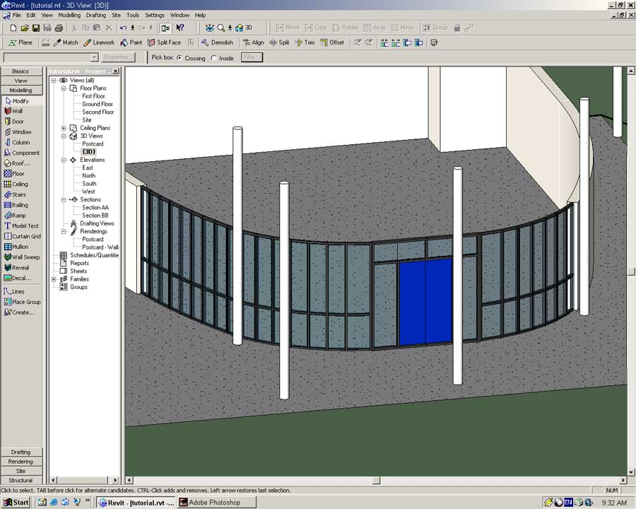
With a little luck and patience you should have something similar to the following.
For those of you wanting a little extra challenge if you look on the plans you will see two garage doors located on the eastern side of the building. Using the same principles as were outlined above it is possible to model these items.
Before we move on we will change the basic wall type to something for fitting of the Villa Savoye.
From the menu select -> Settings -> Materials... -> Duplicate
Name: Villa Savoye Ground Floor Finish (Enter)
Enter the following properties for the material.
Colour: Deep Green
AccuRender Texture: AR2_ACCUREND -> flat, dark green
Press OK
With the Modify tool select the Basic Wall segments.
Press the Properties button. In the Properties dialog under Type press Edit/New -> Duplicate.
Name: Villa Savoye Ground Floor (Enter)
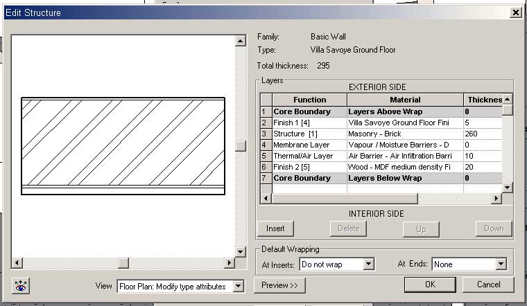
In the Structure field press the Edit button.
The walls of the real Villa Savoye are constructed using rendered concrete block work.
In the Structure dialog set the following parameters:
Press OK all the dialog boxes to accept the changes.
All the ground floor walls, apart from the curtain walls should be the new Object type.